HP ENVY dv4-5b00 HP Envy dv4 Maintenance and Service Guide - Page 59
Optical drive connector cable, from the system board.
 |
View all HP ENVY dv4-5b00 manuals
Add to My Manuals
Save this manual to your list of manuals |
Page 59 highlights
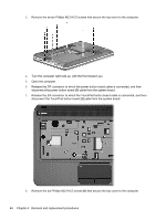
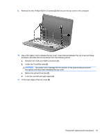
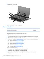
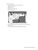
Reverse this procedure to install the TouchPad button board. Optical drive connector cable NOTE: The optical drive connector cable is included in the Optical Drive Hardware Kit, spare part number 681227-001. Before removing the optical drive connector cable, follow these steps: 1. Shut down the computer. 2. Disconnect the power from the computer by unplugging the power cord from the computer. 3. Disconnect all external devices from the computer. 4. Remove the battery (see Battery on page 30), and then remove the following components: a. Service door (see Service door on page 32) b. Hard drive (see Hard drive on page 33) c. Optical drive (see Optical drive on page 36) d. Keyboard (see Keyboard on page 42) e. Top cover (see Top cover on page 45) Remove the optical drive connector cable: 1. Disconnect the optical drive connector cable (1) from the system board. 2. Release the optical drive connector cable from the clip (2) built into the base enclosure. 3. Release the clip (3) built into the base enclosure that secures the optical drive connector to the base enclosure. 4. Remove the optical drive connector cable (4). Reverse this procedure to install the optical drive connector cable. Component replacement procedures 51
-
 1
1 -
2
-
3
-
4
-
5
-
6
-
7
-
8
-
9
-
10
-
11
-
12
-
13
-
14
-
15
-
16
-
17
-
18
-
19
-
20
-
21
-
22
-
23
-
24
-
25
-
26
-
27
-
28
-
29
-
30
-
31
-
32
-
33
-
34
-
35
-
36
-
37
-
38
-
39
-
40
-
41
-
42
-
43
-
44
-
45
-
46
-
47
-
48
-
49
-
50
-
51
-
52
-
53
-
 54
54 -
 55
55 -
 56
56 -
 57
57 -
 58
58 -
 59
59 -
 60
60 -
 61
61 -
 62
62 -
 63
63 -
 64
64 -
65
-
66
-
67
-
68
-
69
-
70
-
71
-
72
-
73
-
74
-
75
-
76
-
77
-
78
-
79
-
80
-
81
-
82
-
83
-
84
-
85
-
86
-
87
-
88
-
89
-
90
-
91
-
92
-
93
-
94
-
95
-
96
 |
 |
