HP ENVY dv4-5b00 HP Envy dv4 Maintenance and Service Guide - Page 55
CAUTION, the optical drive bay when releasing the top cover.
 |
View all HP ENVY dv4-5b00 manuals
Add to My Manuals
Save this manual to your list of manuals |
Page 55 highlights
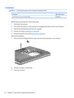
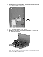
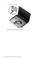
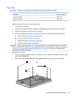
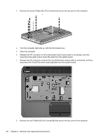
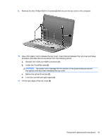
9. Remove the two Phillips M2.0×3.5 screws (2) that secure the top cover to the computer. 10. Use a thin plastic tool to release the top cover. Insert the tool between the top cover and base enclosure and slide the tool as shown from the following points: a. Between the VGA and HDMI connectors (1) b. Under the TouchPad area (2) CAUTION: Be careful not to damage the thin section of the base enclosure around the optical drive bay when releasing the top cover. c. Before the optical drive bay (3) d. From the rear left and right edges (4) 11. Lift the rear edge of the top cover (5). Component replacement procedures 47
-
 1
1 -
2
-
3
-
4
-
5
-
6
-
7
-
8
-
9
-
10
-
11
-
12
-
13
-
14
-
15
-
16
-
17
-
18
-
19
-
20
-
21
-
22
-
23
-
24
-
25
-
26
-
27
-
28
-
29
-
30
-
31
-
32
-
33
-
34
-
35
-
36
-
37
-
38
-
39
-
40
-
41
-
42
-
43
-
44
-
45
-
46
-
47
-
48
-
49
-
 50
50 -
 51
51 -
 52
52 -
 53
53 -
 54
54 -
 55
55 -
 56
56 -
 57
57 -
 58
58 -
 59
59 -
 60
60 -
61
-
62
-
63
-
64
-
65
-
66
-
67
-
68
-
69
-
70
-
71
-
72
-
73
-
74
-
75
-
76
-
77
-
78
-
79
-
80
-
81
-
82
-
83
-
84
-
85
-
86
-
87
-
88
-
89
-
90
-
91
-
92
-
93
-
94
-
95
-
96
 |
 |

9.
Remove the two Phillips M2.0×3.5 screws
(2)
that secure the top cover to the computer.
10.
Use a thin plastic tool to release the top cover. Insert the tool between the top cover and base
enclosure and slide the tool as shown from the following points:
a.
Between the VGA and HDMI connectors
(1)
b.
Under the TouchPad area
(2)
CAUTION:
Be careful not to damage the thin section of the base enclosure around
the optical drive bay when releasing the top cover.
c.
Before the optical drive bay
(3)
d.
From the rear left and right edges
(4)
11.
Lift the rear edge of the top cover
(5)
.
Component replacement procedures
47