HP ENVY dv4-5b00 HP Envy dv4 Maintenance and Service Guide - Page 71
built into the right speaker., from the clips
 |
View all HP ENVY dv4-5b00 manuals
Add to My Manuals
Save this manual to your list of manuals |
Page 71 highlights
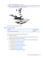
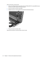
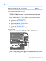
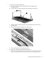
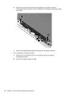
3. Disconnect all external devices from the computer. 4. Remove the battery (see Battery on page 30), and then remove the following components: a. Service door (see Service door on page 32) b. Hard drive (see Hard drive on page 33) c. Optical drive (see Optical drive on page 36) d. WLAN module (see WLAN module on page 39) e. Keyboard (see Keyboard on page 42) f. Top cover (see Top cover on page 45) g. System board (see System board on page 52) h. Power connector cable (see Power connector cable on page 59) Remove the display assembly: 1. Release the wireless antenna cables (1) from the clips (2) built into the right speaker. CAUTION: Support the display assembly when removing the following screws. Failure to support the display assembly can result in damage to the display assembly and other computer components. 2. Remove the three Phillips M2.5×6.5 screws (1) that secure the display assembly to the base enclosure. Component replacement procedures 63
-
 1
1 -
2
-
3
-
4
-
5
-
6
-
7
-
8
-
9
-
10
-
11
-
12
-
13
-
14
-
15
-
16
-
17
-
18
-
19
-
20
-
21
-
22
-
23
-
24
-
25
-
26
-
27
-
28
-
29
-
30
-
31
-
32
-
33
-
34
-
35
-
36
-
37
-
38
-
39
-
40
-
41
-
42
-
43
-
44
-
45
-
46
-
47
-
48
-
49
-
50
-
51
-
52
-
53
-
54
-
55
-
56
-
57
-
58
-
59
-
60
-
61
-
62
-
63
-
64
-
65
-
 66
66 -
 67
67 -
 68
68 -
 69
69 -
 70
70 -
 71
71 -
 72
72 -
 73
73 -
 74
74 -
 75
75 -
 76
76 -
77
-
78
-
79
-
80
-
81
-
82
-
83
-
84
-
85
-
86
-
87
-
88
-
89
-
90
-
91
-
92
-
93
-
94
-
95
-
96
 |
 |
