HP ENVY dv4-5b00 HP Envy dv4 Maintenance and Service Guide - Page 70
Display assembly, Before removing the display assembly, follow these steps
 |
View all HP ENVY dv4-5b00 manuals
Add to My Manuals
Save this manual to your list of manuals |
Page 70 highlights
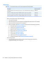
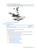
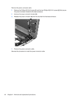
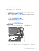
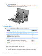
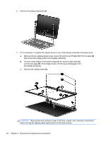
4. Remove the speakers (3). NOTE: The speakers include four rubber isolators that are installed in the screw holes (4). These isolators are crucial to the performance of the speakers. Reverse this procedure to install the speakers. Display assembly NOTE: The display assembly is spared at the subcomponent level only. Description 35.6 cm (14.0 in), LED. HD, BrightView display panel (includes 2 rubber screw covers) Antenna Kit (includes left and right wireless antenna cables and transceivers and 2 rubber screw covers) Display bezel (includes 2 rubber screw covers) Display enclosure (includes 2 rubber screw covers): In black licorice finish In carmine red finish Display Hinge Kit (includes left and right hinges and 2 rubber screw covers) Display panel cable (includes webcamera/microphone module cable and 2 rubber screw covers) Webcamera/microphone module (includes 2 rubber screw covers) Spare part number 676653-001 676640-001 700547-001 676641-001 678260-001 676648-001 676646-001 676659-001 Before removing the display assembly, follow these steps: 1. Shut down the computer. 2. Disconnect the power from the computer by unplugging the power cord from the computer. 62 Chapter 4 Removal and replacement procedures
-
 1
1 -
2
-
3
-
4
-
5
-
6
-
7
-
8
-
9
-
10
-
11
-
12
-
13
-
14
-
15
-
16
-
17
-
18
-
19
-
20
-
21
-
22
-
23
-
24
-
25
-
26
-
27
-
28
-
29
-
30
-
31
-
32
-
33
-
34
-
35
-
36
-
37
-
38
-
39
-
40
-
41
-
42
-
43
-
44
-
45
-
46
-
47
-
48
-
49
-
50
-
51
-
52
-
53
-
54
-
55
-
56
-
57
-
58
-
59
-
60
-
61
-
62
-
63
-
64
-
 65
65 -
 66
66 -
 67
67 -
 68
68 -
 69
69 -
 70
70 -
 71
71 -
 72
72 -
 73
73 -
 74
74 -
 75
75 -
76
-
77
-
78
-
79
-
80
-
81
-
82
-
83
-
84
-
85
-
86
-
87
-
88
-
89
-
90
-
91
-
92
-
93
-
94
-
95
-
96
 |
 |
