HP EliteBook 2170p HP EliteBook 2170p Notebook PC Maintenance and Service Guid - Page 73
Remove the two Torx TM2.0×3.7 screws from the docking station alignment guide holes
 |
View all HP EliteBook 2170p manuals
Add to My Manuals
Save this manual to your list of manuals |
Page 73 highlights
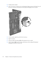
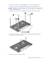
5. Remove the two rubber screw covers (1) and (2) in the rear corners of the base enclosure. The rubber screw covers are included in the Rubber Kit, spare part number 693355-001. NOTE: The rubber screw covers are different sizes. The longer rubber screw cover (2) should be installed in the rear/right corner. 6. Remove the ten Torx TM2.0×5.6 screws (3) that secure the base enclosure to the computer. 7. Remove the two Torx TM2.0×3.7 screws from the docking station alignment guide holes that secure the base enclosure to the computer. 8. Position the computer with the front toward you. Component replacement procedures 65
-
 1
1 -
2
-
3
-
4
-
5
-
6
-
7
-
8
-
9
-
10
-
11
-
12
-
13
-
14
-
15
-
16
-
17
-
18
-
19
-
20
-
21
-
22
-
23
-
24
-
25
-
26
-
27
-
28
-
29
-
30
-
31
-
32
-
33
-
34
-
35
-
36
-
37
-
38
-
39
-
40
-
41
-
42
-
43
-
44
-
45
-
46
-
47
-
48
-
49
-
50
-
51
-
52
-
53
-
54
-
55
-
56
-
57
-
58
-
59
-
60
-
61
-
62
-
63
-
64
-
65
-
66
-
67
-
 68
68 -
 69
69 -
 70
70 -
 71
71 -
 72
72 -
 73
73 -
 74
74 -
 75
75 -
 76
76 -
 77
77 -
 78
78 -
79
-
80
-
81
-
82
-
83
-
84
-
85
-
86
-
87
-
88
-
89
-
90
-
91
-
92
-
93
-
94
-
95
-
96
-
97
-
98
-
99
-
100
-
101
-
102
-
103
-
104
-
105
-
106
-
107
-
108
-
109
-
110
-
111
-
112
-
113
-
114
-
115
-
116
-
117
-
118
 |
 |

5.
Remove the two rubber screw covers
(1)
and
(2)
in the rear corners of the base enclosure.
The rubber screw covers are included in the Rubber Kit, spare part number 693355-001.
NOTE:
The rubber screw covers are different sizes. The longer rubber screw cover
(2)
should be
installed in the rear/right corner.
6.
Remove the ten Torx TM2.0×5.6 screws
(3)
that secure the base enclosure to the computer.
7.
Remove the two Torx TM2.0×3.7 screws from the docking station alignment guide holes that
secure the base enclosure to the computer.
8.
Position the computer with the front toward you.
Component replacement procedures
65