HP EliteBook 2170p HP EliteBook 2170p Notebook PC Maintenance and Service Guid - Page 88
Top cover
 |
View all HP EliteBook 2170p manuals
Add to My Manuals
Save this manual to your list of manuals |
Page 88 highlights
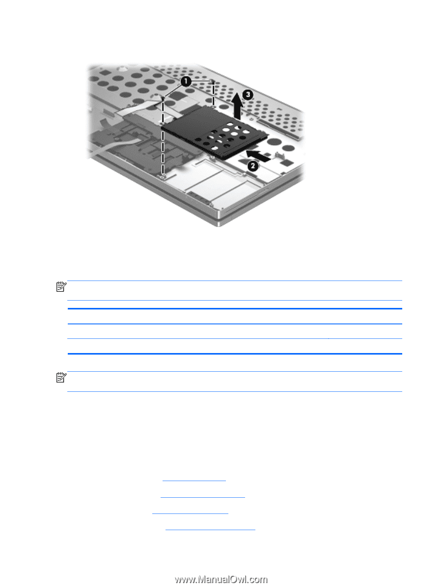
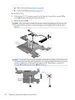
3. Remove the Smart Card reader assembly (3). Reverse this procedure to install the Smart Card reader assembly. Top cover NOTE: The top cover spare part kit includes the TouchPad. The TouchPad cable is included in the Cable Kit, spare part number 693306-001. Description For use on computer models equipped with a fingerprint reader For use on computer models not equipped with a fingerprint reader Spare part number 693317-001 694507-001 NOTE: The display assembly is spared at the subcomponent level only. For more display assembly spare part information, see the individual removal subsections. Before removing the display assembly, follow these steps: 1. Turn off the computer. If you are unsure whether the computer is off or in Hibernation, turn the computer on, and then shut it down through the operating system. 2. Disconnect the power from the computer by unplugging the power cord from the computer. 3. Disconnect all external devices from the computer. 4. Remove the battery (see Battery on page 45), and then remove the following components: a. Service cover (see Service cover on page 47) b. Hard drive (see Hard drive on page 48) c. WLAN module (see WLAN module on page 51) 80 Chapter 4 Removal and replacement procedures
-
 1
1 -
2
-
3
-
4
-
5
-
6
-
7
-
8
-
9
-
10
-
11
-
12
-
13
-
14
-
15
-
16
-
17
-
18
-
19
-
20
-
21
-
22
-
23
-
24
-
25
-
26
-
27
-
28
-
29
-
30
-
31
-
32
-
33
-
34
-
35
-
36
-
37
-
38
-
39
-
40
-
41
-
42
-
43
-
44
-
45
-
46
-
47
-
48
-
49
-
50
-
51
-
52
-
53
-
54
-
55
-
56
-
57
-
58
-
59
-
60
-
61
-
62
-
63
-
64
-
65
-
66
-
67
-
68
-
69
-
70
-
71
-
72
-
73
-
74
-
75
-
76
-
77
-
78
-
79
-
80
-
81
-
82
-
 83
83 -
 84
84 -
 85
85 -
 86
86 -
 87
87 -
 88
88 -
 89
89 -
 90
90 -
 91
91 -
 92
92 -
 93
93 -
94
-
95
-
96
-
97
-
98
-
99
-
100
-
101
-
102
-
103
-
104
-
105
-
106
-
107
-
108
-
109
-
110
-
111
-
112
-
113
-
114
-
115
-
116
-
117
-
118
 |
 |