HP EliteBook 2170p HP EliteBook 2170p Notebook PC Maintenance and Service Guid - Page 89
Release the left-side wireless antenna cables, from the clips
 |
View all HP EliteBook 2170p manuals
Add to My Manuals
Save this manual to your list of manuals |
Page 89 highlights
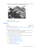
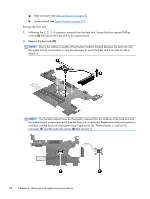
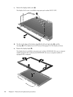
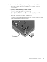
d. WWAN module (see WWAN module on page 53) e. Fan (see Fan on page 57) f. Keyboard (see Keyboard on page 58) g. Base enclosure (see Base enclosure on page 63) h. System board (see System board on page 75) NOTE: When replacing the top cover, be sure to remove the following components from the defective top cover and install them on the replacement top cover: ● Fingerprint reader board (see Fingerprint reader board on page 50) ● Media Card reader assembly (see Media Card reader assembly on page 71) ● Smart Card reader assembly (see Smart Card reader assembly on page 79) Remove the top cover: 1. Release the left-side wireless antenna cables (1) from the clips (2) and routing channel built into the top cover. 2. Release the display panel cable (3) and right-side wireless antenna cables from the clips (4) and routing channel built into the top cover. 3. Remove the two Phillips PM2.0×5.0 screws (5) that secure the top cover to the display assembly. Component replacement procedures 81
-
 1
1 -
2
-
3
-
4
-
5
-
6
-
7
-
8
-
9
-
10
-
11
-
12
-
13
-
14
-
15
-
16
-
17
-
18
-
19
-
20
-
21
-
22
-
23
-
24
-
25
-
26
-
27
-
28
-
29
-
30
-
31
-
32
-
33
-
34
-
35
-
36
-
37
-
38
-
39
-
40
-
41
-
42
-
43
-
44
-
45
-
46
-
47
-
48
-
49
-
50
-
51
-
52
-
53
-
54
-
55
-
56
-
57
-
58
-
59
-
60
-
61
-
62
-
63
-
64
-
65
-
66
-
67
-
68
-
69
-
70
-
71
-
72
-
73
-
74
-
75
-
76
-
77
-
78
-
79
-
80
-
81
-
82
-
83
-
 84
84 -
 85
85 -
 86
86 -
 87
87 -
 88
88 -
 89
89 -
 90
90 -
 91
91 -
 92
92 -
 93
93 -
 94
94 -
95
-
96
-
97
-
98
-
99
-
100
-
101
-
102
-
103
-
104
-
105
-
106
-
107
-
108
-
109
-
110
-
111
-
112
-
113
-
114
-
115
-
116
-
117
-
118
 |
 |