HP EliteBook 2170p HP EliteBook 2170p Notebook PC Maintenance and Service Guid - Page 87
Smart Card reader assembly
 |
View all HP EliteBook 2170p manuals
Add to My Manuals
Save this manual to your list of manuals |
Page 87 highlights
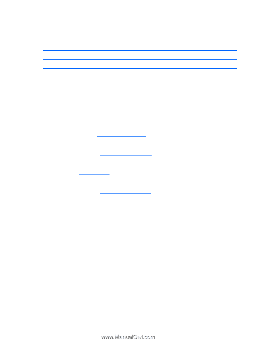
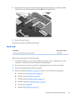
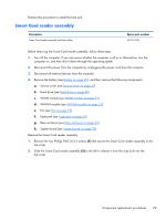
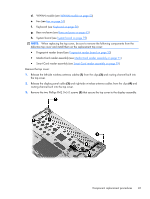
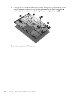
Reverse this procedure to install the heat sink. Smart Card reader assembly Description Smart Card reader assembly (includes cable) Spare part number 693312-001 Before removing the Smart Card reader assembly, follow these steps: 1. Turn off the computer. If you are unsure whether the computer is off or in Hibernation, turn the computer on, and then shut it down through the operating system. 2. Disconnect the power from the computer by unplugging the power cord from the computer. 3. Disconnect all external devices from the computer. 4. Remove the battery (see Battery on page 45), and then remove the following components: a. Service cover (see Service cover on page 47) b. Hard drive (see Hard drive on page 48) c. WLAN module (see WLAN module on page 51) d. WWAN module (see WWAN module on page 53) e. Fan (see Fan on page 57) f. Keyboard (see Keyboard on page 58) g. Base enclosure (see Base enclosure on page 63) h. System board (see System board on page 75) Remove the Smart Card reader assembly: 1. Remove the two Phillips PM2.0×3.4 screws (1) that secure the Smart Card reader assembly to the top cover. 2. Slide the Smart Card reader assembly (2) to the left to release it from the clips built into the top cover. Component replacement procedures 79
-
 1
1 -
2
-
3
-
4
-
5
-
6
-
7
-
8
-
9
-
10
-
11
-
12
-
13
-
14
-
15
-
16
-
17
-
18
-
19
-
20
-
21
-
22
-
23
-
24
-
25
-
26
-
27
-
28
-
29
-
30
-
31
-
32
-
33
-
34
-
35
-
36
-
37
-
38
-
39
-
40
-
41
-
42
-
43
-
44
-
45
-
46
-
47
-
48
-
49
-
50
-
51
-
52
-
53
-
54
-
55
-
56
-
57
-
58
-
59
-
60
-
61
-
62
-
63
-
64
-
65
-
66
-
67
-
68
-
69
-
70
-
71
-
72
-
73
-
74
-
75
-
76
-
77
-
78
-
79
-
80
-
81
-
 82
82 -
 83
83 -
 84
84 -
 85
85 -
 86
86 -
 87
87 -
 88
88 -
 89
89 -
 90
90 -
 91
91 -
 92
92 -
93
-
94
-
95
-
96
-
97
-
98
-
99
-
100
-
101
-
102
-
103
-
104
-
105
-
106
-
107
-
108
-
109
-
110
-
111
-
112
-
113
-
114
-
115
-
116
-
117
-
118
 |
 |