HP EliteBook 2170p HP EliteBook 2170p Notebook PC Maintenance and Service Guid - Page 84
front of the computer., and swing it up and forward until it rests upside down
 |
View all HP EliteBook 2170p manuals
Add to My Manuals
Save this manual to your list of manuals |
Page 84 highlights
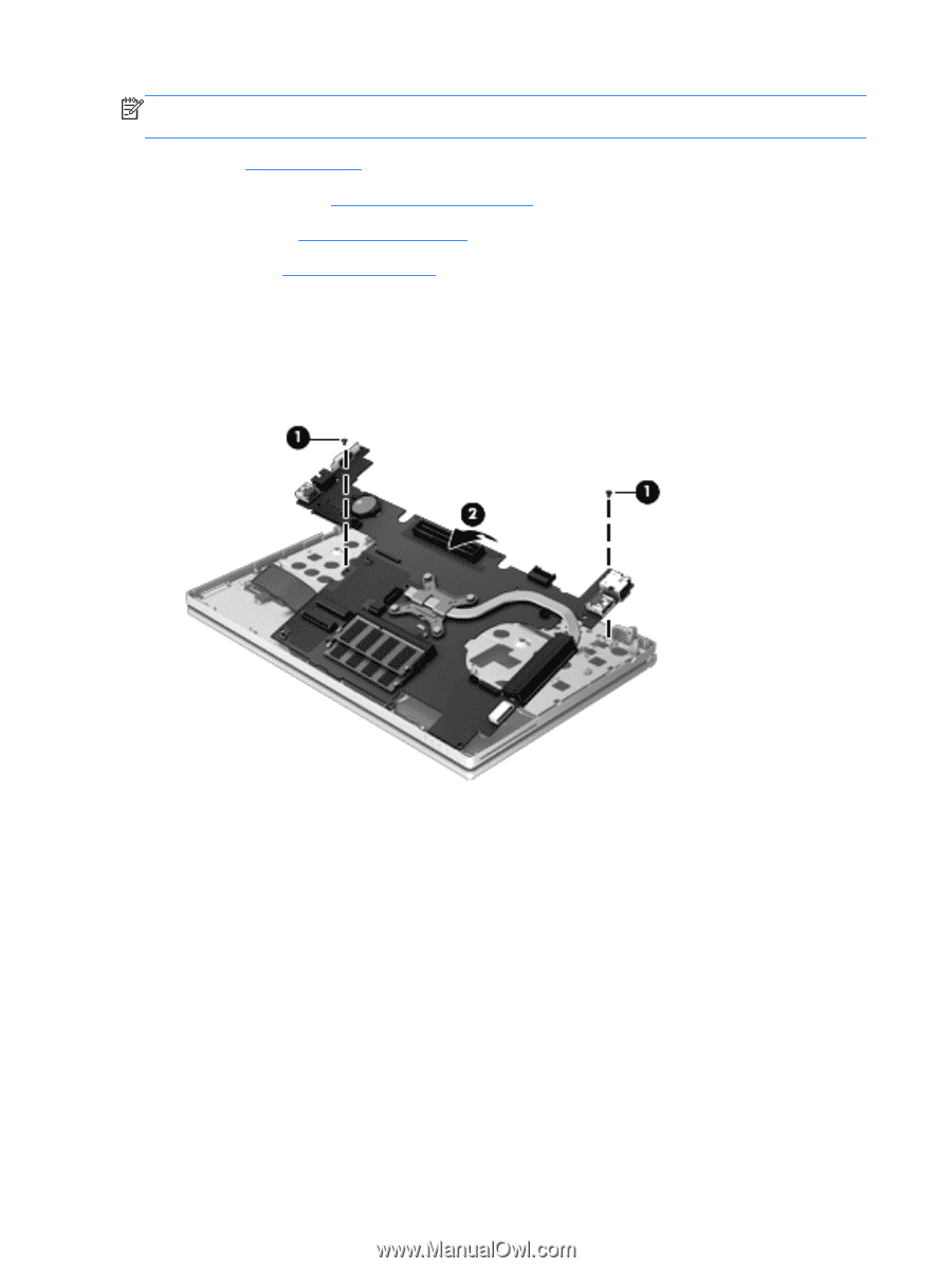
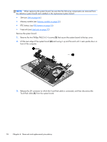
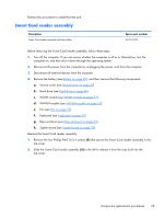
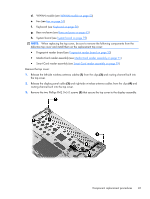
NOTE: When replacing the system board, be sure that the following components are removed from the defective system board and installed on the replacement system board: ● SIM (see SIM on page 46) ● Memory module (see Memory module on page 55) ● RTC battery (see RTC battery on page 73) ● Heat sink (see Heat sink on page 77) Remove the system board: 1. Remove the two Phillips PM2.0×3.4 screws (1) that secure the system board to the top cover. 2. Lift the rear edge of the system board (2) and swing it up and forward until it rests upside down in front of the computer. 3. Release the ZIF connector to which the TouchPad cable is connected, and then disconnect the TouchPad cable (1) from the system board. 76 Chapter 4 Removal and replacement procedures
-
 1
1 -
2
-
3
-
4
-
5
-
6
-
7
-
8
-
9
-
10
-
11
-
12
-
13
-
14
-
15
-
16
-
17
-
18
-
19
-
20
-
21
-
22
-
23
-
24
-
25
-
26
-
27
-
28
-
29
-
30
-
31
-
32
-
33
-
34
-
35
-
36
-
37
-
38
-
39
-
40
-
41
-
42
-
43
-
44
-
45
-
46
-
47
-
48
-
49
-
50
-
51
-
52
-
53
-
54
-
55
-
56
-
57
-
58
-
59
-
60
-
61
-
62
-
63
-
64
-
65
-
66
-
67
-
68
-
69
-
70
-
71
-
72
-
73
-
74
-
75
-
76
-
77
-
78
-
 79
79 -
 80
80 -
 81
81 -
 82
82 -
 83
83 -
 84
84 -
 85
85 -
 86
86 -
 87
87 -
 88
88 -
 89
89 -
90
-
91
-
92
-
93
-
94
-
95
-
96
-
97
-
98
-
99
-
100
-
101
-
102
-
103
-
104
-
105
-
106
-
107
-
108
-
109
-
110
-
111
-
112
-
113
-
114
-
115
-
116
-
117
-
118
 |
 |