HP Model 735 hp workstation 9000 series model 735 - service handboook - Page 17
System, Unit Rear Panel Connectors
 |
View all HP Model 735 manuals
Add to My Manuals
Save this manual to your list of manuals |
Page 17 highlights
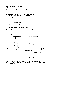
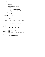
.! System Unit Rear Panel Connectors This section describes the four main 1/0 subsystems on the system unit's rear panel: q System 1/0 Connectors q Graphic 1/0 Connectors q Disk 1/0 Connectors q EISA 1/0 Connectors Figure 1- 5 shows the location of the connectors as well as the ac power connector on"the system's rear panel. NOTICE: To maintain FCC/EMI compliance, verify that all cables are fully seated and properly fastened. Figure 1 -5. Model 735 Rear Panel Connectors Product Information 1-7
-
 1
1 -
2
-
3
-
4
-
5
-
6
-
7
-
8
-
9
-
10
-
11
-
 12
12 -
 13
13 -
 14
14 -
 15
15 -
 16
16 -
 17
17 -
 18
18 -
 19
19 -
 20
20 -
 21
21 -
 22
22 -
23
-
24
-
25
-
26
-
27
-
28
-
29
-
30
-
31
-
32
-
33
-
34
-
35
-
36
-
37
-
38
-
39
-
40
-
41
-
42
-
43
-
44
-
45
-
46
-
47
-
48
-
49
-
50
-
51
-
52
-
53
-
54
-
55
-
56
-
57
-
58
-
59
-
60
-
61
-
62
-
63
-
64
-
65
-
66
-
67
-
68
-
69
-
70
-
71
-
72
-
73
-
74
-
75
-
76
-
77
-
78
-
79
-
80
-
81
-
82
-
83
-
84
-
85
-
86
-
87
 |
 |

System
Unit Rear Panel Connectors
This section describes the four main 1/0 subsystems on the system unit’s rear
panel:
System 1/0 Connectors
Graphic 1/0 Connectors
Disk 1/0 Connectors
EISA 1/0 Connectors
Figure 1– 5 shows the location of the connectors as well as the ac power connector
on”the system’s rear panel.
NOTICE:
To maintain FCC/EMI compliance, verify
that all cables are fully seated and properly
fastened.
Figure1–5.
Model 735 Rear Panel Connectors
Product Information
1-7