HP Model 735 hp workstation 9000 series model 735 - service handboook - Page 39
Installing, Additional, Memory
 |
View all HP Model 735 manuals
Add to My Manuals
Save this manual to your list of manuals |
Page 39 highlights
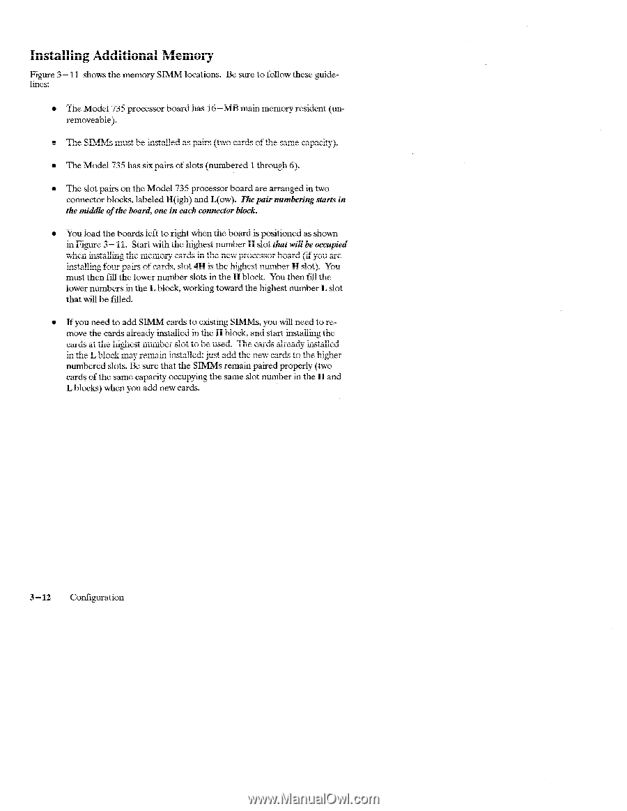
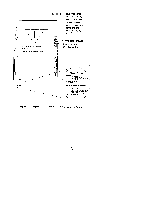
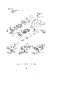
Installing Additional Memory Figure 3 - 11 shows the memory SIMM locations. Be sure to follow these guidelines: . The Model 735 processor board has 16-MB main memory resident (unremovable). . The SIMMS must be installed as pairs (two cards of the same capacity). . The Model 735 has six pairs of slots (numbered 1 through 6). . The slot pairs on the Model 735 processor board are arranged in two connector blocks. labeled H(igh) and L(ow). The pair numbem"ngstarts in the middle of the board, one in each connector block. q You load the boards left to right when the board is positioned as shown in Figure 3 - 11. Startwith the highest number H slot that will be occupied when installing the memory cards in the new processor board (if you are installing four pairs of cards, slot 4H is the highest number H slot). You must then fill the lower number slots in the H block. You then fill the lower numbers in the L block, working toward the highest number L slot that will be filled. . If you need to add SIMM cards to existing SIMMS, you will need to remove the cards already installed in the H block, and start installing the cards at the highest number slot to be used. The cards already installed in the L block may remain installed; just add the new cards to the higher numbered slots. Be sure that the SIMMS remain paired properly (two cards of the same capacity occupying the same slot number in the H and L blocks) when you add new cards. 3-12 Configuration
-
 1
1 -
2
-
3
-
4
-
5
-
6
-
7
-
8
-
9
-
10
-
11
-
12
-
13
-
14
-
15
-
16
-
17
-
18
-
19
-
20
-
21
-
22
-
23
-
24
-
25
-
26
-
27
-
28
-
29
-
30
-
31
-
32
-
33
-
 34
34 -
 35
35 -
 36
36 -
 37
37 -
 38
38 -
 39
39 -
 40
40 -
 41
41 -
 42
42 -
 43
43 -
 44
44 -
45
-
46
-
47
-
48
-
49
-
50
-
51
-
52
-
53
-
54
-
55
-
56
-
57
-
58
-
59
-
60
-
61
-
62
-
63
-
64
-
65
-
66
-
67
-
68
-
69
-
70
-
71
-
72
-
73
-
74
-
75
-
76
-
77
-
78
-
79
-
80
-
81
-
82
-
83
-
84
-
85
-
86
-
87
 |
 |