HP Model 735 hp workstation 9000 series model 735 - service handboook - Page 75
Field Replaceable Units
 |
View all HP Model 735 manuals
Add to My Manuals
Save this manual to your list of manuals |
Page 75 highlights
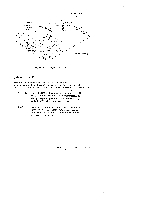
. The Model 735 processor board has 16-MB main memory resident (unremovable). Therefore. the upgraded system will have 16 MB more main memory than the original system. . The SIMMS must be installed as pairs (two cards of the same capacity). . The Model 735 has six pairs of slots (numbered 1 through 6). . The slot pairs on the Model 735 processor board are arranged in two connec- tor blocks, labeled H(igh) and L(ow). The pair numbering starts in the middle of the board, one in each connector block. q You load the boards left to right when the board is positioned as shown in Chapter 3. Startwith the highest number H slot that will be occupied when installing the memory cards in the new processor board (if you are installing four pan-sof cards, slot 4H is the highest number H slot). You must then fill the lower number slots in the H block. You then fill the lower numbers in the L block, working toward the highest number L slot that will be filled. . If you later need to add more SIMM cards, you will need to remove the cards already installed in the H block, and start installing the cards at the highest number slot to be used. The cards already installed in the L block may remain installed; just add the new cards to the higher numbered slots. Be sure that the SIMMS remain paired properly (two cards of the same capacity occupying the salineslot number in the H and L blocks) when you add new cards. Field Replaceable Units 5-15
-
 1
1 -
2
-
3
-
4
-
5
-
6
-
7
-
8
-
9
-
10
-
11
-
12
-
13
-
14
-
15
-
16
-
17
-
18
-
19
-
20
-
21
-
22
-
23
-
24
-
25
-
26
-
27
-
28
-
29
-
30
-
31
-
32
-
33
-
34
-
35
-
36
-
37
-
38
-
39
-
40
-
41
-
42
-
43
-
44
-
45
-
46
-
47
-
48
-
49
-
50
-
51
-
52
-
53
-
54
-
55
-
56
-
57
-
58
-
59
-
60
-
61
-
62
-
63
-
64
-
65
-
66
-
67
-
68
-
69
-
 70
70 -
 71
71 -
 72
72 -
 73
73 -
 74
74 -
 75
75 -
 76
76 -
 77
77 -
 78
78 -
 79
79 -
 80
80 -
81
-
82
-
83
-
84
-
85
-
86
-
87
 |
 |
