HP Model 735 hp workstation 9000 series model 735 - service handboook - Page 7

Table of Contents

Page 7 highlights

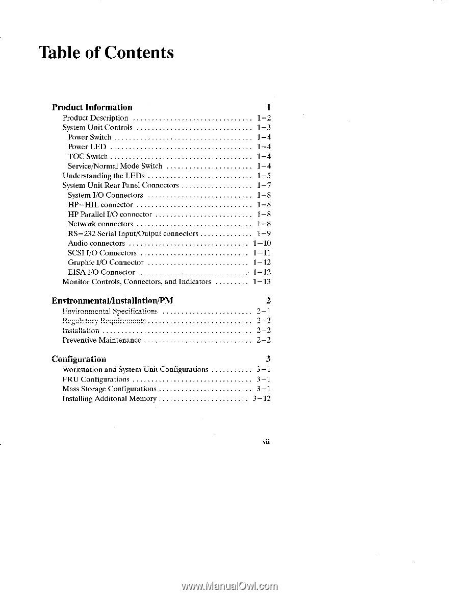
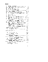
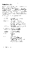
Table of Contents Product Information 1 Product Description 1-2 System Unit Controls OO. 1-3 Power Switch 1-4 Power LED 1-4 TOCSwitch 1-4 Service/NormalModeSwitch... 1-4 UnderstandingtheL Ems...... 1-5 System Unit Rear Panel Connectors 1-7 SystemI/OConnectors 1-8 HP-HIL connector 1-8 HPParallelI/Oconnector 1-8 Network connectors 1-8 RS-232SerialInput/Outputconnectors 1-9 Audio connectors 1-10 SCSII/OConnectors 1-11 GraphicI/OConnector 1-12 EISAI/OConnector 1-12 Monitor Controls, Connectors, and Indicators 1-13 Environmental/Installation/PM 2 Environmental Specifications 2-1 Regulatory Requirements 2-2 Installation 2-2 Preventive Maintenance 2-2 Configuration 3 Workstation and System Unit Configurations 3-1 FRU Configurations 3-1 Mass Storage Configurations 3-1 InstallingAdditonal Memory 3-12 vii

  • 1
  • 2
  • 3
  • 4
  • 5
  • 6
  • 7
  • 8
  • 9
  • 10
  • 11
  • 12
  • 13
  • 14
  • 15
  • 16
  • 17
  • 18
  • 19
  • 20
  • 21
  • 22
  • 23
  • 24
  • 25
  • 26
  • 27
  • 28
  • 29
  • 30
  • 31
  • 32
  • 33
  • 34
  • 35
  • 36
  • 37
  • 38
  • 39
  • 40
  • 41
  • 42
  • 43
  • 44
  • 45
  • 46
  • 47
  • 48
  • 49
  • 50
  • 51
  • 52
  • 53
  • 54
  • 55
  • 56
  • 57
  • 58
  • 59
  • 60
  • 61
  • 62
  • 63
  • 64
  • 65
  • 66
  • 67
  • 68
  • 69
  • 70
  • 71
  • 72
  • 73
  • 74
  • 75
  • 76
  • 77
  • 78
  • 79
  • 80
  • 81
  • 82
  • 83
  • 84
  • 85
  • 86
  • 87

Table of Contents
Product
Information
1
Product Description
................................
1–2
System Unit Controls
. . . . . . . . . . . . . . . . . . . . . . . . . . ..
OO.
1–3
Power Switch
.....................................
1–4
Power LED
......................................
1–4
TOCSwitch
......................................
1–4
Service/NormalModeSwitch
...
....................
1–4
UnderstandingtheL Ems
......
......................
1–5
System Unit Rear Panel Connectors
...................
1–7
SystemI/OConnectors
............................
1–8
HP–HIL
connector
...............................
1–8
HPParallelI/Oconnector
..........................
1–8
Network connectors
...............................
1–8
RS–232SerialInput/Outputconnectors
..............
1–9
Audio connectors
................................
1–10
SCSII/OConnectors
.............................
1–11
GraphicI/OConnector
...........................
1–12
EISAI/OConnector
.............................
1–12
Monitor
Controls,
Connectors,
and Indicators
.........
1–13
Environmental/Installation/PM
2
Environmental
Specifications
........................
2–1
Regulatory
Requirements
............................
2–2
Installation
........................................
2–2
Preventive Maintenance
.............................
2–2
Configuration
3
Workstation
and System Unit Configurations
...........
3–1
FRU Configurations
................................
3–1
Mass Storage Configurations
..
.......................
3–1
InstallingAdditonal
Memory
...
.....................
3–12
vii