HP Model 735 hp workstation 9000 series model 735 - service handboook - Page 9
HP Model 735 - Workstation Manual
 |
View all HP Model 735 manuals
Add to My Manuals
Save this manual to your list of manuals |
Page 9 highlights
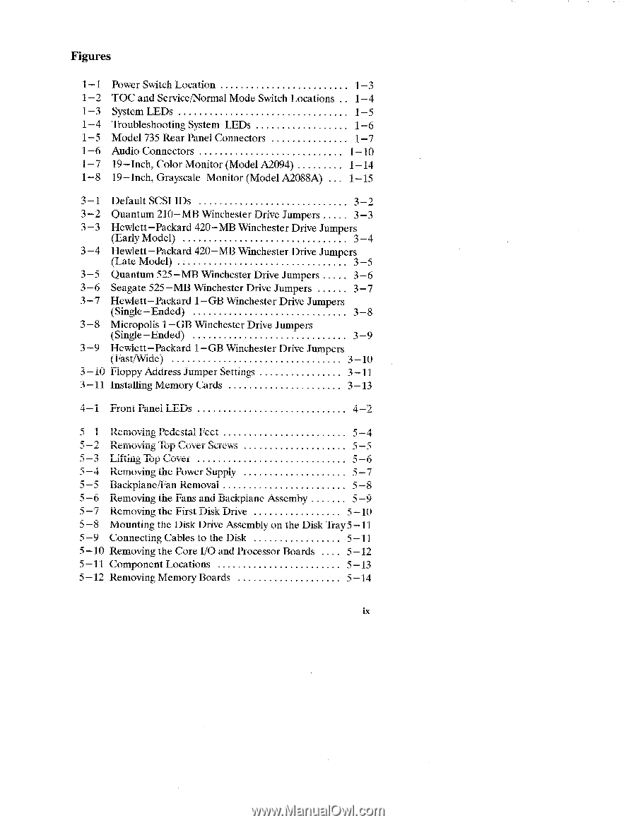
.. Figures 1-1 Power Switch Location 1-3 1-2 TOC and Service/Normal Mode Switch Locations . . 1-4 1-3 System LEDs 1-5 1-4 Troubleshooting System LEDs 1-6 1-5 Mode1735Rear Panel Connectors 1-7 1-6 Audio Connectors 1-10 1-7 19-Inch, Color Monitor (ModelA2094 1-14 1-8 19-Inch, Grayscale Monitor (ModelA2088A) . . . 1-15 3-1 3-2 3-3 3-4 3-5 3-6 3-7 3-8 3-9 3-lo 3-11 DefaultSCSIIDs 3-2 Quantum 210-MB Winchester Drive Jumpers . . . . . 3-3 Hewlett-Packard 420-MBWinchester Drive Jumpers (Early Model 3-4 Hewlett -Packard 420-MB Winchester Drive Jumpers (Late Model 3-5 Quantum 525 -MB Winchester Drive Jumpers . . . . . 3 -6 Seagate 525 -MB Winchester Drive Jumpers 3 -7 Hewlett -Packard 1- GB Winchester Drive Jumpers (Single-Ended 3-8 Micropolis 1- GB Winchester Drive Jumpers (Single-Ended 3-9 Hewlett -Packard 1- GB Winchester Drive Jumpers (Fast/Wide s-10 Floppy Address Jumper Settings 3-11 Installing Memory Cards 3-13 4-1 Front Panel LEDs 4-2 5-1 5-2 5-3 5-4 5-5 5-6 5-7 5-8 5-9 5-lo 5-11 5-12 Removing Pedestal Feet 5-4 Removing Top Cover Screws 5-5 Lifting Top Cover 5-6 Removing the Power Supply 5-7 Backplane/Fan Removal 5-8 Removing the Fans and Backplane Assemby 5-9 Removing the First Disk Drive 5-10 Mounting the Disk Drive Assembly on the Disk Tray 5 - 11 Connecting Cables tothe Disk 5-11 Removing the Core I/Oand Processor Boards . . . . 5-12 Component Locations 5-13 Removing Memory Boards 5-14 ix
-
 1
1 -
2
-
3
-
 4
4 -
 5
5 -
 6
6 -
 7
7 -
 8
8 -
 9
9 -
 10
10 -
 11
11 -
 12
12 -
 13
13 -
 14
14 -
15
-
16
-
17
-
18
-
19
-
20
-
21
-
22
-
23
-
24
-
25
-
26
-
27
-
28
-
29
-
30
-
31
-
32
-
33
-
34
-
35
-
36
-
37
-
38
-
39
-
40
-
41
-
42
-
43
-
44
-
45
-
46
-
47
-
48
-
49
-
50
-
51
-
52
-
53
-
54
-
55
-
56
-
57
-
58
-
59
-
60
-
61
-
62
-
63
-
64
-
65
-
66
-
67
-
68
-
69
-
70
-
71
-
72
-
73
-
74
-
75
-
76
-
77
-
78
-
79
-
80
-
81
-
82
-
83
-
84
-
85
-
86
-
87
 |
 |