HP Model 735 hp workstation 9000 series model 735 - service handboook - Page 8

lloubleshooting, Field Replaceable, Units, Diagrams, Reference, Service Notes

Page 8 highlights

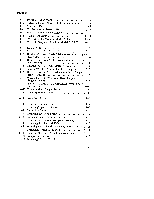
.' 'lloubleshooting 4 LED Error Codes 4-2 Dealingwith a Boot Failure 4-12 Boot Administration Environment 4-13 Stable Storage 4-14 Boot Command Notations 4-15 Supported Foot paths 4-15 Invoking the ISLEnvironment froma SCSI Device . . . 4-15 ISLEnvironment 4-17 ISLUser Commands 4-17 Running the Disk-BasedISL Diagnostics 4-18 Verifying the System Operation with SupportWave . . . . . 4-19 Field Replaceable Units 5 Pedestal Feet 5-4 Top Cover 5-5 Power Supply o 5-7 Backplane/FanAssembly 5-8 Disk Drives 5-10 CoreI/OandProcessorBoard.. 5-12 System EEPROM 5-13 Memory 5-14 Calendar Battery 5-16 LANSliderModule 5-17 Graphics Board 5-18 FrontControlPanel 5-19 Diagrams 6 Reference 7 Installation Manual 7-1 Service Manuals 7-1 Reference Manuals 7-1 Service Notes 8 Vmq 00

  • 1
  • 2
  • 3
  • 4
  • 5
  • 6
  • 7
  • 8
  • 9
  • 10
  • 11
  • 12
  • 13
  • 14
  • 15
  • 16
  • 17
  • 18
  • 19
  • 20
  • 21
  • 22
  • 23
  • 24
  • 25
  • 26
  • 27
  • 28
  • 29
  • 30
  • 31
  • 32
  • 33
  • 34
  • 35
  • 36
  • 37
  • 38
  • 39
  • 40
  • 41
  • 42
  • 43
  • 44
  • 45
  • 46
  • 47
  • 48
  • 49
  • 50
  • 51
  • 52
  • 53
  • 54
  • 55
  • 56
  • 57
  • 58
  • 59
  • 60
  • 61
  • 62
  • 63
  • 64
  • 65
  • 66
  • 67
  • 68
  • 69
  • 70
  • 71
  • 72
  • 73
  • 74
  • 75
  • 76
  • 77
  • 78
  • 79
  • 80
  • 81
  • 82
  • 83
  • 84
  • 85
  • 86
  • 87

.’
‘lloubleshooting
4
LED Error Codes
..............
...................
4–2
Dealingwith
a Boot Failure
.........................
4–12
Boot Administration
Environment
..................
4–13
Stable Storage
...................................
4–14
Boot Command
Notations
........................
4–15
Supported
Foot
paths
............................
4–15
Invoking the ISLEnvironment
froma
SCSI Device
...
4–15
ISLEnvironment
................................
4–17
ISLUser
Commands
.............................
4–17
Running the Disk–BasedISL
Diagnostics
...........
4–18
Verifying the System Operation
with SupportWave
.....
4–19
Field Replaceable
Units
5
Pedestal Feet
......................................
5–4
Top Cover
.........................................
5–5
Power Supply
. . . . . . ..
o
......
.......................
5–7
Backplane/FanAssembly
............................
5–8
Disk Drives
......................................
5–10
CoreI/OandProcessorBoard
..
.....................
5–12
System EEPROM
................................
5–13
Memory
........................................
5–14
Calendar Battery
..................................
5–16
LANSliderModule
...............................
5–17
Graphics Board
...................................
5–18
FrontControlPanel
...............................
5–19
Diagrams
6
Reference
7
Installation Manual
.................................
7–1
Service Manuals
...................................
7–1
Reference
Manuals
.................................
7–1
Service Notes
8
00
Vm