HP Model 735 hp workstation 9000 series model 735 - service handboook - Page 84
data storage
 |
View all HP Model 735 manuals
Add to My Manuals
Save this manual to your list of manuals |
Page 84 highlights
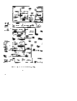
B block diagram, 6-2 boot admin mode, 4- 13 boot command notations, 4- 15 boot failure, 4- 12 boot paths, 4- 15 boot ROM diagnostics, 4- 1 c calendar battery removal, 5 - 16 configuration FRU, 3- 1 mass storage, 3 - 1 memory, 3 - 12 connectors monitor, 1- 13 system unit, 1-7 ac, 1-7 audio, 1- 10 graphics, 1- 12 HP-HIL, 1-8 network, 1-8 parallel, 1-8 RS-232, 1-9 serial, 1-9 Controls monitor, 1- 13 system unit, 1-3 CPU components locations, 5-13 CPU removal, 5 - 12 D diagnostics, 4- 1 boot ROM, 4-1 diagrams, block diagram, 6-2 documentation, reference, 7- 1 E EEPROM, data storage, 5 - 13 environmental specifications, 2-1 F fan removal, 5 -9 first disk removal, 5 - 10 front control panel removal, 5-19 FRU configuration, 3 - 1 FRU parts list, 5 -2 FRU removal calendar battery, 5 - 16 CPU, 5 -12 fan, 5 -9 first disk, 5 - 10 front control panel, 5 - 19 memory, 5 - 14 pedestal feet, 5 -4 power supply, 5 -7 Index- 1
-
 1
1 -
2
-
3
-
4
-
5
-
6
-
7
-
8
-
9
-
10
-
11
-
12
-
13
-
14
-
15
-
16
-
17
-
18
-
19
-
20
-
21
-
22
-
23
-
24
-
25
-
26
-
27
-
28
-
29
-
30
-
31
-
32
-
33
-
34
-
35
-
36
-
37
-
38
-
39
-
40
-
41
-
42
-
43
-
44
-
45
-
46
-
47
-
48
-
49
-
50
-
51
-
52
-
53
-
54
-
55
-
56
-
57
-
58
-
59
-
60
-
61
-
62
-
63
-
64
-
65
-
66
-
67
-
68
-
69
-
70
-
71
-
72
-
73
-
74
-
75
-
76
-
77
-
78
-
 79
79 -
 80
80 -
 81
81 -
 82
82 -
 83
83 -
 84
84 -
 85
85 -
 86
86 -
 87
87
 |
 |
