HP Pavilion m7-1000 HP Pavilion dv7 Entertainment PC - Maintenance and Service - Page 67
to which the keyboard backlight cable is, Release the zero insertion force ZIF connector
 |
View all HP Pavilion m7-1000 manuals
Add to My Manuals
Save this manual to your list of manuals |
Page 67 highlights
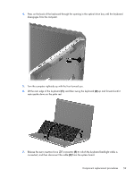
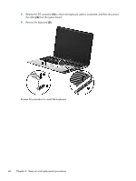
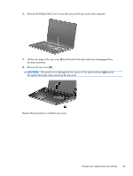
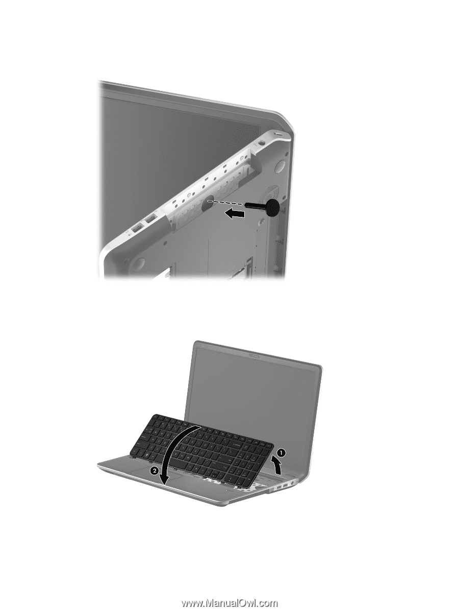
4. Press on the back of the keyboard through the opening in the optical drive bay until the keyboard disengages from the computer. 5. Turn the computer right-side up with the front toward you. 6. Lift the rear edge of the keyboard (1), and then swing the keyboard (2) up and forward until it rests upside down on the palm rest. 7. Release the zero insertion force (ZIF) connector (1) to which the keyboard backlight cable is connected, and then disconnect the cable (2) from the system board. Component replacement procedures 59
-
 1
1 -
2
-
3
-
4
-
5
-
6
-
7
-
8
-
9
-
10
-
11
-
12
-
13
-
14
-
15
-
16
-
17
-
18
-
19
-
20
-
21
-
22
-
23
-
24
-
25
-
26
-
27
-
28
-
29
-
30
-
31
-
32
-
33
-
34
-
35
-
36
-
37
-
38
-
39
-
40
-
41
-
42
-
43
-
44
-
45
-
46
-
47
-
48
-
49
-
50
-
51
-
52
-
53
-
54
-
55
-
56
-
57
-
58
-
59
-
60
-
61
-
 62
62 -
 63
63 -
 64
64 -
 65
65 -
 66
66 -
 67
67 -
 68
68 -
 69
69 -
 70
70 -
 71
71 -
 72
72 -
73
-
74
-
75
-
76
-
77
-
78
-
79
-
80
-
81
-
82
-
83
-
84
-
85
-
86
-
87
-
88
-
89
-
90
-
91
-
92
-
93
-
94
-
95
-
96
-
97
-
98
-
99
-
100
-
101
-
102
-
103
-
104
-
105
-
106
-
107
-
108
-
109
-
110
-
111
-
112
-
113
-
114
-
115
-
116
-
117
-
118
-
119
-
120
-
121
-
122
-
123
-
124
 |
 |
4.
Press on the back of the keyboard through the opening in the optical drive bay until the keyboard
disengages from the computer.
5.
Turn the computer right-side up with the front toward you.
6.
Lift the rear edge of the keyboard
(1)
, and then swing the keyboard
(2)
up and forward until it
rests upside down on the palm rest.
7.
Release the zero insertion force (ZIF) connector
(1)
to which the keyboard backlight cable is
connected, and then disconnect the cable
(2)
from the system board.
Component replacement procedures
59