HP Pavilion m7-1000 HP Pavilion dv7 Entertainment PC - Maintenance and Service - Page 85
System board see, Remove the fan/heat sink assembly
 |
View all HP Pavilion m7-1000 manuals
Add to My Manuals
Save this manual to your list of manuals |
Page 85 highlights
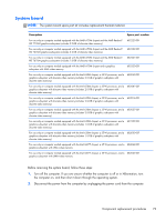
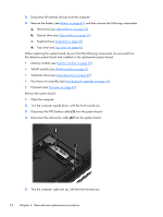
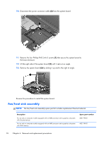
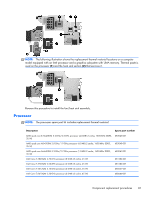
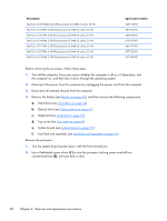
Description Spare part number For use only on computer models equipped with an Intel processor and a graphics subsystem with 682061-001 discrete memory For use only on computer models equipped with an Intel processor and a graphics subsystem with 682060-001 UMA memory NOTE: To properly ventilate the computer, allow at least 7.6 cm (3 in) of clearance on the left side of the computer. The computer uses an electric fan for ventilation. The fan is controlled by a temperature sensor and is designed to turn on automatically when high temperature conditions exist. These conditions are affected by high external temperatures, system power consumption, power management/battery conservation configurations, battery fast charging, and software requirements. Exhaust air is displaced through the ventilation grill located on the left side of the computer. Before removing the fan/heat sink assembly, follow these steps: 1. Turn off the computer. If you are unsure whether the computer is off or in Hibernation, turn the computer on, and then shut it down through the operating system. 2. Disconnect the power from the computer by unplugging the power cord from the computer. 3. Disconnect all external devices from the computer. 4. Remove the battery (see Battery on page 45), and then remove the following components: a. Hard drive (see Hard drive on page 46) b. Optical drive (see Optical drive on page 51) c. Keyboard (see Keyboard on page 57) d. Top cover (see Top cover on page 61) e. System board (see System board on page 73) Remove the fan/heat sink assembly: 1. Turn the system board upside down, with the front toward you. NOTE: Steps 2 and 3 apply to computer models equipped with a graphics subsystem with discrete memory. See steps 4 and 5 for fan/heat sink assembly removal information for computer models equipped with a graphics subsystem with UMA memory. 2. Disconnect the fan cable (1) from the system board. Component replacement procedures 77
-
 1
1 -
2
-
3
-
4
-
5
-
6
-
7
-
8
-
9
-
10
-
11
-
12
-
13
-
14
-
15
-
16
-
17
-
18
-
19
-
20
-
21
-
22
-
23
-
24
-
25
-
26
-
27
-
28
-
29
-
30
-
31
-
32
-
33
-
34
-
35
-
36
-
37
-
38
-
39
-
40
-
41
-
42
-
43
-
44
-
45
-
46
-
47
-
48
-
49
-
50
-
51
-
52
-
53
-
54
-
55
-
56
-
57
-
58
-
59
-
60
-
61
-
62
-
63
-
64
-
65
-
66
-
67
-
68
-
69
-
70
-
71
-
72
-
73
-
74
-
75
-
76
-
77
-
78
-
79
-
 80
80 -
 81
81 -
 82
82 -
 83
83 -
 84
84 -
 85
85 -
 86
86 -
 87
87 -
 88
88 -
 89
89 -
 90
90 -
91
-
92
-
93
-
94
-
95
-
96
-
97
-
98
-
99
-
100
-
101
-
102
-
103
-
104
-
105
-
106
-
107
-
108
-
109
-
110
-
111
-
112
-
113
-
114
-
115
-
116
-
117
-
118
-
119
-
120
-
121
-
122
-
123
-
124
 |
 |