HP Pavilion m7-1000 HP Pavilion dv7 Entertainment PC - Maintenance and Service - Page 80
the base enclosure., and routing channel built into
 |
View all HP Pavilion m7-1000 manuals
Add to My Manuals
Save this manual to your list of manuals |
Page 80 highlights
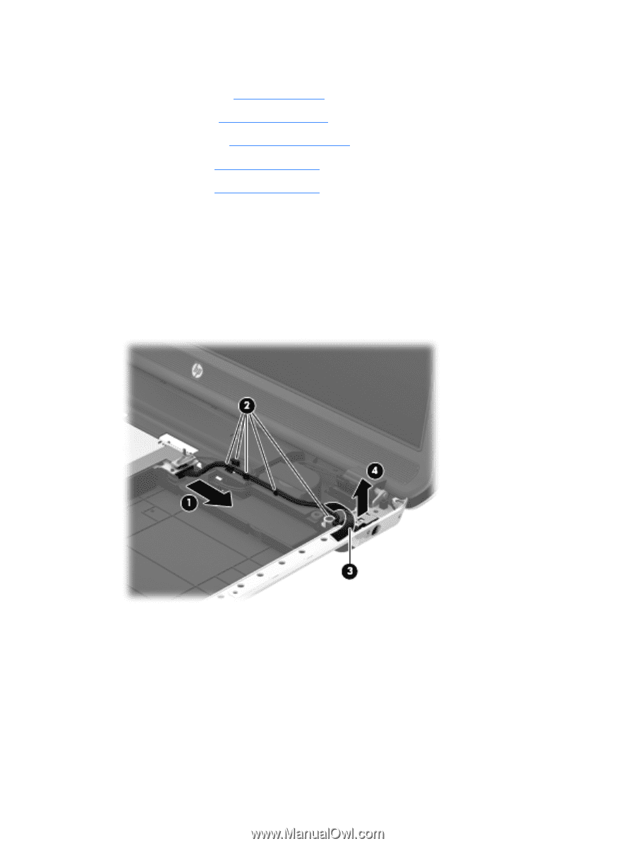
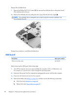
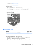
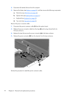
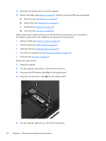
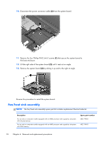
3. Disconnect all external devices from the computer. 4. Remove the battery (see Battery on page 45), and then remove the following components: a. Hard drive (see Hard drive on page 46) b. Optical drive (see Optical drive on page 51) c. Keyboard (see Keyboard on page 57) d. Top cover (see Top cover on page 61) Remove the power connector cable: 1. Disconnect the power connector cable (1) from the system board. 2. Release the power connector cable from the clips (2) and routing channel built into the base enclosure. 3. Release the tape that secures the power connector (3) to the base enclosure. 4. Release the power connector (4) from the clip built into the base enclosure. Reverse this procedure to install the power connector cable. 72 Chapter 4 Removal and replacement procedures
-
 1
1 -
2
-
3
-
4
-
5
-
6
-
7
-
8
-
9
-
10
-
11
-
12
-
13
-
14
-
15
-
16
-
17
-
18
-
19
-
20
-
21
-
22
-
23
-
24
-
25
-
26
-
27
-
28
-
29
-
30
-
31
-
32
-
33
-
34
-
35
-
36
-
37
-
38
-
39
-
40
-
41
-
42
-
43
-
44
-
45
-
46
-
47
-
48
-
49
-
50
-
51
-
52
-
53
-
54
-
55
-
56
-
57
-
58
-
59
-
60
-
61
-
62
-
63
-
64
-
65
-
66
-
67
-
68
-
69
-
70
-
71
-
72
-
73
-
74
-
 75
75 -
 76
76 -
 77
77 -
 78
78 -
 79
79 -
 80
80 -
 81
81 -
 82
82 -
 83
83 -
 84
84 -
 85
85 -
86
-
87
-
88
-
89
-
90
-
91
-
92
-
93
-
94
-
95
-
96
-
97
-
98
-
99
-
100
-
101
-
102
-
103
-
104
-
105
-
106
-
107
-
108
-
109
-
110
-
111
-
112
-
113
-
114
-
115
-
116
-
117
-
118
-
119
-
120
-
121
-
122
-
123
-
124
 |
 |