HP Pavilion m7-1000 HP Pavilion dv7 Entertainment PC - Maintenance and Service - Page 96
Display assembly, Remove the display assembly
 |
View all HP Pavilion m7-1000 manuals
Add to My Manuals
Save this manual to your list of manuals |
Page 96 highlights
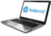
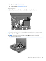
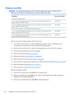
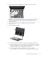
Display assembly NOTE: The display assembly spare part kit includes display panel cable, 2 WLAN antenna transceivers and cables, and webcamera/microphone module and cable. Description For use on all computer models: 17.3-in, FHD, AntiGlare display assembly for use only on computer models equipped with a graphics subsystem with UMA memory 17.3-in, HD, BrightView display assembly for use only on computer models equipped with a graphics subsystem with UMA memory For use only with computer models equipped with an Intel processor: 17.3-in, FHD, AntiGlare display assembly for use only on computer models equipped with a graphics subsystem with discrete memory 17.3-in, HD, BrightView display assembly for use only on computer models equipped with a graphics subsystem with discrete memory Spare part number 681979-001 681978-001 682228-001 682227-001 Before removing the display assembly, follow these steps: 1. Turn off the computer. If you are unsure whether the computer is off or in Hibernation, turn the computer on, and then shut it down through the operating system. 2. Disconnect the power from the computer by unplugging the power cord from the computer. 3. Disconnect all external devices from the computer. 4. Remove the battery (see Battery on page 45). 5. Remove the hard drive (see Hard drive on page 46). 6. Remove the optical drive (see Optical drive on page 51). 7. Disconnect the wireless antenna cables from the WLAN module (see WLAN module on page 55). 8. Remove the keyboard (see Keyboard on page 57). 9. Remove the top cover (see Top cover on page 61). Remove the display assembly: 1. Disconnect the display panel cable (1) from the system board. 2. Release the display panel cable (2) from the heat sink. (The display panel cable is attached to the heat sink with double-sided tape.) 3. Disconnect the display speakers cable (3) from the system board. 88 Chapter 4 Removal and replacement procedures
-
 1
1 -
2
-
3
-
4
-
5
-
6
-
7
-
8
-
9
-
10
-
11
-
12
-
13
-
14
-
15
-
16
-
17
-
18
-
19
-
20
-
21
-
22
-
23
-
24
-
25
-
26
-
27
-
28
-
29
-
30
-
31
-
32
-
33
-
34
-
35
-
36
-
37
-
38
-
39
-
40
-
41
-
42
-
43
-
44
-
45
-
46
-
47
-
48
-
49
-
50
-
51
-
52
-
53
-
54
-
55
-
56
-
57
-
58
-
59
-
60
-
61
-
62
-
63
-
64
-
65
-
66
-
67
-
68
-
69
-
70
-
71
-
72
-
73
-
74
-
75
-
76
-
77
-
78
-
79
-
80
-
81
-
82
-
83
-
84
-
85
-
86
-
87
-
88
-
89
-
90
-
 91
91 -
 92
92 -
 93
93 -
 94
94 -
 95
95 -
 96
96 -
 97
97 -
 98
98 -
 99
99 -
 100
100 -
 101
101 -
102
-
103
-
104
-
105
-
106
-
107
-
108
-
109
-
110
-
111
-
112
-
113
-
114
-
115
-
116
-
117
-
118
-
119
-
120
-
121
-
122
-
123
-
124
 |
 |