HP Pavilion m7-1000 HP Pavilion dv7 Entertainment PC - Maintenance and Service - Page 94
Optical drive connector cable, Optical drive, on Battery, Hard drive, Keyboard, Top cover
 |
View all HP Pavilion m7-1000 manuals
Add to My Manuals
Save this manual to your list of manuals |
Page 94 highlights
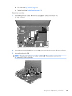
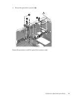
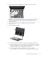
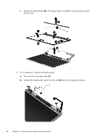
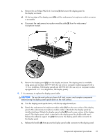
Reverse this procedure to install the subwoofer. Optical drive connector cable NOTE: The optical drive connector cable is included in the optical drive spare part kit. See Optical drive on page 51 for optical drive spare part number information. Before removing the optical drive connector cable, follow these steps: 1. Turn off the computer. If you are unsure whether the computer is off or in Hibernation, turn the computer on, and then shut it down through the operating system. 2. Disconnect the power from the computer by unplugging the power cord from the computer. 3. Disconnect all external devices from the computer. 4. Remove the battery (see Battery on page 45), and then remove the following components: a. Hard drive (see Hard drive on page 46) b. Optical drive (see Optical drive on page 51) c. Keyboard (see Keyboard on page 57) d. Top cover (see Top cover on page 61) e. System board (see System board on page 73) f. Subwoofer (see Subwoofer on page 84) Remove the optical drive connector cable: 1. Release the optical drive connector cable (1) from the clips and routing channel built into the base enclosure. 2. Remove the two Phillips PM2.0×4.0 screws (2) that secure the optical drive connector cable to the base enclosure. 86 Chapter 4 Removal and replacement procedures
-
 1
1 -
2
-
3
-
4
-
5
-
6
-
7
-
8
-
9
-
10
-
11
-
12
-
13
-
14
-
15
-
16
-
17
-
18
-
19
-
20
-
21
-
22
-
23
-
24
-
25
-
26
-
27
-
28
-
29
-
30
-
31
-
32
-
33
-
34
-
35
-
36
-
37
-
38
-
39
-
40
-
41
-
42
-
43
-
44
-
45
-
46
-
47
-
48
-
49
-
50
-
51
-
52
-
53
-
54
-
55
-
56
-
57
-
58
-
59
-
60
-
61
-
62
-
63
-
64
-
65
-
66
-
67
-
68
-
69
-
70
-
71
-
72
-
73
-
74
-
75
-
76
-
77
-
78
-
79
-
80
-
81
-
82
-
83
-
84
-
85
-
86
-
87
-
88
-
 89
89 -
 90
90 -
 91
91 -
 92
92 -
 93
93 -
 94
94 -
 95
95 -
 96
96 -
 97
97 -
 98
98 -
 99
99 -
100
-
101
-
102
-
103
-
104
-
105
-
106
-
107
-
108
-
109
-
110
-
111
-
112
-
113
-
114
-
115
-
116
-
117
-
118
-
119
-
120
-
121
-
122
-
123
-
124
 |
 |