HP Pavilion m7-1000 HP Pavilion dv7 Entertainment PC - Maintenance and Service - Page 84
Fan/heat sink assembly, Remove the system board
 |
View all HP Pavilion m7-1000 manuals
Add to My Manuals
Save this manual to your list of manuals |
Page 84 highlights
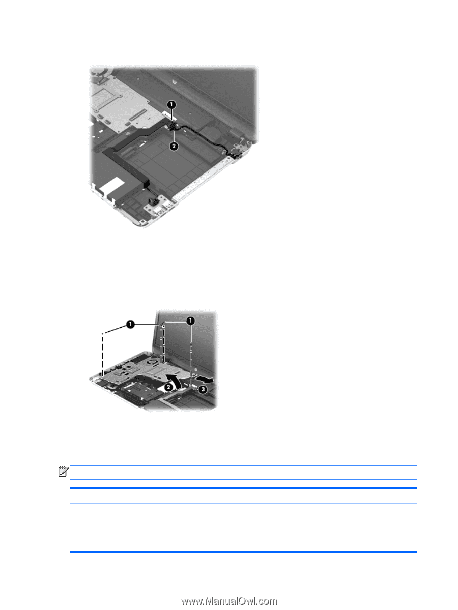
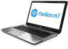
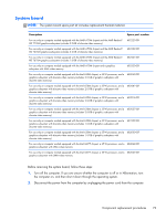
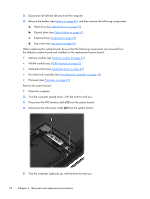
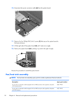
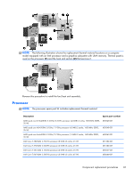
10. Disconnect the power connector cable (2) from the system board. 11. Remove the four Phillips PM2.5×6.0 screws (1) that secure the system board to the base enclosure. 12. Lift the right side of the system board (2) until it rests at an angle. 13. Remove the system board (3) by sliding it up and to the right at angle. Reverse this procedure to install the system board. Fan/heat sink assembly NOTE: The fan/heat sink assembly spare part kit includes replacement thermal material. Description For use only on computer models equipped with an AMD processor and a graphics subsystem with discrete memory For use only on computer models equipped with an AMD processor and a graphics subsystem with UMA memory Spare part number 682179-001 682178-001 76 Chapter 4 Removal and replacement procedures
-
 1
1 -
2
-
3
-
4
-
5
-
6
-
7
-
8
-
9
-
10
-
11
-
12
-
13
-
14
-
15
-
16
-
17
-
18
-
19
-
20
-
21
-
22
-
23
-
24
-
25
-
26
-
27
-
28
-
29
-
30
-
31
-
32
-
33
-
34
-
35
-
36
-
37
-
38
-
39
-
40
-
41
-
42
-
43
-
44
-
45
-
46
-
47
-
48
-
49
-
50
-
51
-
52
-
53
-
54
-
55
-
56
-
57
-
58
-
59
-
60
-
61
-
62
-
63
-
64
-
65
-
66
-
67
-
68
-
69
-
70
-
71
-
72
-
73
-
74
-
75
-
76
-
77
-
78
-
 79
79 -
 80
80 -
 81
81 -
 82
82 -
 83
83 -
 84
84 -
 85
85 -
 86
86 -
 87
87 -
 88
88 -
 89
89 -
90
-
91
-
92
-
93
-
94
-
95
-
96
-
97
-
98
-
99
-
100
-
101
-
102
-
103
-
104
-
105
-
106
-
107
-
108
-
109
-
110
-
111
-
112
-
113
-
114
-
115
-
116
-
117
-
118
-
119
-
120
-
121
-
122
-
123
-
124
 |
 |