HP R1500 HP 3 Phase UPS User Guide - Page 22
Connecting to a normally-closed contact, load loss. For more information
 |
View all HP R1500 manuals
Add to My Manuals
Save this manual to your list of manuals |
Page 22 highlights
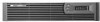
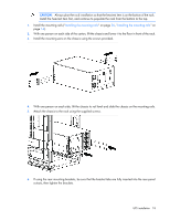
NOTE: The REPO wiring of a standalone UPS can be connected with the REPO wiring of a parallel system if the same sense (NO or NC) contacts are used. Be sure to match the polarity for the contacts. 1. Verify that the UPS is powered down and all power sources are removed. For more information, see "Powering down the standalone UPS (on page 72)." 2. Mount the remote REPO switch. HP recommends mounting the REPO switch near the operator's consoles or near the exit doors. For enclosure dimensions and wiring knockouts, see the REPO switch manufacturer's installation instructions. 3. Connect the appropriate external switch to terminal block 4, normally-open REPO. IMPORTANT: Always test the REPO function before applying the critical load to avoid accidental load loss. For more information, see "Verifying the REPO port connection (on page 71)." 4. Reconnect terminal block 4, normally-open REPO, and then power on the UPS manually to restart. Pins should remain open to keep the UPS running. Maximum resistance is 10 ohm. 5. Verify that the jumper is inserted in terminal block 5. Connecting to a normally-closed contact IMPORTANT: The remote switch must be in the closed position to enable power to the UPS output. NOTE: The REPO wiring of a standalone UPS can be connected with the REPO wiring of a parallel system if the same sense (NO or NC) contacts are used. Be sure to match the polarity for the contacts. UPS installation 22
-
 1
1 -
2
-
3
-
4
-
5
-
6
-
7
-
8
-
9
-
10
-
11
-
12
-
13
-
14
-
15
-
16
-
 17
17 -
 18
18 -
 19
19 -
 20
20 -
 21
21 -
 22
22 -
 23
23 -
 24
24 -
 25
25 -
 26
26 -
 27
27 -
28
-
29
-
30
-
31
-
32
-
33
-
34
-
35
-
36
-
37
-
38
-
39
-
40
-
41
-
42
-
43
-
44
-
45
-
46
-
47
-
48
-
49
-
50
-
51
-
52
-
53
-
54
-
55
-
56
-
57
-
58
-
59
-
60
-
61
-
62
-
63
-
64
-
65
-
66
-
67
-
68
-
69
-
70
-
71
-
72
-
73
-
74
-
75
-
76
-
77
-
78
-
79
-
80
-
81
-
82
-
83
-
84
-
85
-
86
-
87
-
88
-
89
-
90
-
91
-
92
-
93
-
94
-
95
-
96
-
97
-
98
-
99
-
100
-
101
-
102
-
103
-
104
-
105
-
106
-
107
-
108
-
109
-
110
-
111
-
112
-
113
-
114
-
115
 |
 |
