HP R1500 HP 3 Phase UPS User Guide - Page 82
Disconnecting the control panel from the electronics module automatically transfers
 |
View all HP R1500 manuals
Add to My Manuals
Save this manual to your list of manuals |
Page 82 highlights
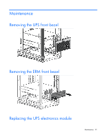
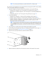
NOTE: Do not disconnect the electronics module while the UPS is in Battery mode. This component is hot-swappable and can be replaced without powering down the UPS. However, Battery mode is not available and the load is not protected. 1. (optional) To replace the component with the UPS powered down, do one of the following: o Standalone UPS configuration-See "Powering down the standalone UPS (on page 72)." o Individual UPS in a parallel configuration-See "Powering down an individual paralleled UPS (on page 72)." o Parallel UPS configuration-See "Powering down the parallel system (on page 73)." 2. Do one of the following: o Standalone UPS configuration-Transfer the UPS to Auto-Bypass mode (on page 66). o Parallel for capacity configuration-Transfer the UPS to Auto-Bypass mode (on page 66). o Parallel for redundancy configuration-No mode transfer is necessary. If the UPS is operating in a parallel for redundancy configuration when the electronics module is replaces, the load automatically transfers to the remaining UPSs. NOTE: Disconnecting the control panel from the electronics module automatically transfers the UPS to Auto-Bypass mode. However, HP recommends transferring the UPS to Auto-Bypass mode manually BEFORE disconnecting the control panel to provide extra protection to the electronics module. 3. If the configuration is parallel, disconnect the redundant signal cable(s) from the UPS. For the location of the redundant signal cable, see "Configuring the Parallel UPS Card (on page 41)." 4. Remove the UPS front bezel ("Removing the UPS front bezel" on page 81). 5. Remove the screw securing the electronics module and slide the module out. 6. Replace the electronics module. Be sure the electronics module is firmly seated in the connector. Maintenance 82
-
 1
1 -
2
-
3
-
4
-
5
-
6
-
7
-
8
-
9
-
10
-
11
-
12
-
13
-
14
-
15
-
16
-
17
-
18
-
19
-
20
-
21
-
22
-
23
-
24
-
25
-
26
-
27
-
28
-
29
-
30
-
31
-
32
-
33
-
34
-
35
-
36
-
37
-
38
-
39
-
40
-
41
-
42
-
43
-
44
-
45
-
46
-
47
-
48
-
49
-
50
-
51
-
52
-
53
-
54
-
55
-
56
-
57
-
58
-
59
-
60
-
61
-
62
-
63
-
64
-
65
-
66
-
67
-
68
-
69
-
70
-
71
-
72
-
73
-
74
-
75
-
76
-
 77
77 -
 78
78 -
 79
79 -
 80
80 -
 81
81 -
 82
82 -
 83
83 -
 84
84 -
 85
85 -
 86
86 -
 87
87 -
88
-
89
-
90
-
91
-
92
-
93
-
94
-
95
-
96
-
97
-
98
-
99
-
100
-
101
-
102
-
103
-
104
-
105
-
106
-
107
-
108
-
109
-
110
-
111
-
112
-
113
-
114
-
115
 |
 |
