HP R1500 HP 3 Phase UPS User Guide - Page 8
UPS front panel
 |
View all HP R1500 manuals
Add to My Manuals
Save this manual to your list of manuals |
Page 8 highlights
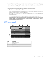
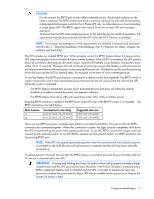
The Power Bus Bar for parallel systems, mounted in the rear of an HP rack, provides the required input and output connections for the paralleled UPSs and has a single system-rated input connection. The parallel UPS system can be installed with Output Power Modules or connected to rack-mounted power distribution systems. Note these guidelines when configuring the UPS standalone unit or parallel system: • There is a maximum of four ERMs per UPS. • Mount ERM(s) for a standalone UPS directly below the UPS or, with rack side panels removed, in an adjacent rack to the left of the rack containing the UPS. • Mount ERMs for a parallel system in an adjacent rack to the left of the rack containing the UPSs (rack side panels removed). • For consistent runtimes, each UPS in a parallel system should have the same number of ERMs. • Some load equipment may require phase rotation or phase relationship coordination to ensure proper operation. Review your equipment manufacturer's power requirement documents to ensure that your connected equipment operates correctly. UPS front panel Item 1 2 3 4 Description Battery compartment Control buttons LED display Electronics compartment Component identification 8
-
 1
1 -
2
-
 3
3 -
 4
4 -
 5
5 -
 6
6 -
 7
7 -
 8
8 -
 9
9 -
 10
10 -
 11
11 -
 12
12 -
 13
13 -
14
-
15
-
16
-
17
-
18
-
19
-
20
-
21
-
22
-
23
-
24
-
25
-
26
-
27
-
28
-
29
-
30
-
31
-
32
-
33
-
34
-
35
-
36
-
37
-
38
-
39
-
40
-
41
-
42
-
43
-
44
-
45
-
46
-
47
-
48
-
49
-
50
-
51
-
52
-
53
-
54
-
55
-
56
-
57
-
58
-
59
-
60
-
61
-
62
-
63
-
64
-
65
-
66
-
67
-
68
-
69
-
70
-
71
-
72
-
73
-
74
-
75
-
76
-
77
-
78
-
79
-
80
-
81
-
82
-
83
-
84
-
85
-
86
-
87
-
88
-
89
-
90
-
91
-
92
-
93
-
94
-
95
-
96
-
97
-
98
-
99
-
100
-
101
-
102
-
103
-
104
-
105
-
106
-
107
-
108
-
109
-
110
-
111
-
112
-
113
-
114
-
115
 |
 |
