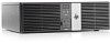
HP RP3 Maintenance & Service Guide HP RP3 Retail System Model 3100 - Page 35
Installing the Powered USB Expansion Card in the Riser Card, Connecting the 12-volt Powered USB Cable
 |
View all HP RP3 manuals
Add to My Manuals
Save this manual to your list of manuals |
Page 35 highlights
6. Install the Powered USB expansion card into the PCI Express x1 socket on the riser card. Move the card toward the rear of the chassis so that the bracket on the card is aligned with the open slot on the rear of the chassis (1). Press the card straight down into the expansion socket on the riser card (2). Figure 4-3 Installing the Powered USB Expansion Card in the Riser Card 7. The cable included with the card has a single connector on one end and dual connectors on the other end. All three connectors are keyed to ensure proper connection. Connect the single end of the cable to the rear of the card (1). Connect the green connector on the other end of the cable to the green USB connector on the system board (2). Connect the black cable connector to the black USB connector on the system board (3). NOTE: The green USB connector on the system board has two rows of pins. You can attach the green cable from the card to either row. Figure 4-4 Connecting the 12-volt Powered USB Cable 28 Chapter 4 Removal and Replacement Procedures
-
 1
1 -
2
-
3
-
4
-
5
-
6
-
7
-
8
-
9
-
10
-
11
-
12
-
13
-
14
-
15
-
16
-
17
-
18
-
19
-
20
-
21
-
22
-
23
-
24
-
25
-
26
-
27
-
28
-
29
-
 30
30 -
 31
31 -
 32
32 -
 33
33 -
 34
34 -
 35
35 -
 36
36 -
 37
37 -
 38
38 -
 39
39 -
 40
40 -
41
-
42
-
43
-
44
-
45
-
46
-
47
-
48
-
49
-
50
-
51
-
52
-
53
-
54
-
55
-
56
-
57
-
58
-
59
-
60
-
61
-
62
-
63
-
64
-
65
-
66
-
67
-
68
-
69
-
70
-
71
-
72
-
73
-
74
-
75
-
76
-
77
-
78
-
79
-
80
-
81
-
82
-
83
-
84
-
85
-
86
-
87
-
88
-
89
-
90
-
91
-
92
-
93
-
94
-
95
-
96
-
97
-
98
-
99
-
100
-
101
-
102
-
103
-
104
-
105
-
106
-
107
-
108
-
109
-
110
-
111
-
112
-
113
-
114
-
115
-
116
-
117
-
118
-
119
-
120
-
121
-
122
-
123
-
124
-
125
-
126
-
127
-
128
-
129
-
130
-
131
-
132
-
133
-
134
-
135
-
136
-
137
-
138
-
139
-
140
 |
 |
