HP RP3 Maintenance & Service Guide HP RP3 Retail System Model 3100 - Page 51
System Board
 |
View all HP RP3 manuals
Add to My Manuals
Save this manual to your list of manuals |
Page 51 highlights
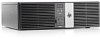
System Board Description System board (includes Intel Celeron 807UE processor; includes thermal material) Spare part number 682426-001 The system board includes a non-removable Intel Celeron 807UE processor soldered to the board. 1. Prepare the computer for disassembly (Preparation for Disassembly on page 15). 2. Remove the access panel (Access Panel on page 16). 3. Remove the riser card cage Riser Card on page 29. 4. Remove the fan assembly (Front Fan/Baffle on page 38). 5. When replacing the system board, make sure the following components are removed from the defective system board and installed on the replacement system board: ● Memory modules (Memory on page 20) ● Expansion cards (Expansion Cards on page 22) 6. Disconnect all data, power, and any other cables from the system board. 7. Remove the seven screws that secure the system board to the floor of the chassis. 8. Slide the system board tray assembly toward the front of the chassis to disengage the rear ports, and then lift the system board up and out of the chassis. To install the system board, reverse the removal procedure. 44 Chapter 4 Removal and Replacement Procedures
-
 1
1 -
2
-
3
-
4
-
5
-
6
-
7
-
8
-
9
-
10
-
11
-
12
-
13
-
14
-
15
-
16
-
17
-
18
-
19
-
20
-
21
-
22
-
23
-
24
-
25
-
26
-
27
-
28
-
29
-
30
-
31
-
32
-
33
-
34
-
35
-
36
-
37
-
38
-
39
-
40
-
41
-
42
-
43
-
44
-
45
-
 46
46 -
 47
47 -
 48
48 -
 49
49 -
 50
50 -
 51
51 -
 52
52 -
 53
53 -
 54
54 -
 55
55 -
 56
56 -
57
-
58
-
59
-
60
-
61
-
62
-
63
-
64
-
65
-
66
-
67
-
68
-
69
-
70
-
71
-
72
-
73
-
74
-
75
-
76
-
77
-
78
-
79
-
80
-
81
-
82
-
83
-
84
-
85
-
86
-
87
-
88
-
89
-
90
-
91
-
92
-
93
-
94
-
95
-
96
-
97
-
98
-
99
-
100
-
101
-
102
-
103
-
104
-
105
-
106
-
107
-
108
-
109
-
110
-
111
-
112
-
113
-
114
-
115
-
116
-
117
-
118
-
119
-
120
-
121
-
122
-
123
-
124
-
125
-
126
-
127
-
128
-
129
-
130
-
131
-
132
-
133
-
134
-
135
-
136
-
137
-
138
-
139
-
140
 |
 |
