HP q1335a User Manual - Page 147
Carefully press the DIMM chip into the slot, making sure that it is straight and all the way
 |
View all HP q1335a manuals
Add to My Manuals
Save this manual to your list of manuals |
Page 147 highlights
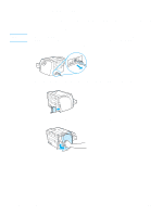
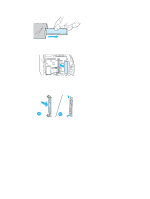
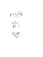
4 Remove the DIMM chip from the antistatic bag it came in, grasping the chip on the top edge. 5 Position the DIMM chip in front of the slot located inside the I/O door. The gold contacts should be pointing toward the printer and the cutouts should be at the top and bottom. 6 Carefully press the DIMM chip into the slot, making sure that it is straight and all the way in (A). The cam latches, located at the top and bottom, should rotate inward. To snap the cam latches into place, press the handles toward each other (B). ENWW Installing a memory DIMM (1300 series only) 139
-
 1
1 -
2
-
3
-
4
-
5
-
6
-
7
-
8
-
9
-
10
-
11
-
12
-
13
-
14
-
15
-
16
-
17
-
18
-
19
-
20
-
21
-
22
-
23
-
24
-
25
-
26
-
27
-
28
-
29
-
30
-
31
-
32
-
33
-
34
-
35
-
36
-
37
-
38
-
39
-
40
-
41
-
42
-
43
-
44
-
45
-
46
-
47
-
48
-
49
-
50
-
51
-
52
-
53
-
54
-
55
-
56
-
57
-
58
-
59
-
60
-
61
-
62
-
63
-
64
-
65
-
66
-
67
-
68
-
69
-
70
-
71
-
72
-
73
-
74
-
75
-
76
-
77
-
78
-
79
-
80
-
81
-
82
-
83
-
84
-
85
-
86
-
87
-
88
-
89
-
90
-
91
-
92
-
93
-
94
-
95
-
96
-
97
-
98
-
99
-
100
-
101
-
102
-
103
-
104
-
105
-
106
-
107
-
108
-
109
-
110
-
111
-
112
-
113
-
114
-
115
-
116
-
117
-
118
-
119
-
120
-
121
-
122
-
123
-
124
-
125
-
126
-
127
-
128
-
129
-
130
-
131
-
132
-
133
-
134
-
135
-
136
-
137
-
138
-
139
-
140
-
141
-
 142
142 -
 143
143 -
 144
144 -
 145
145 -
 146
146 -
 147
147 -
 148
148 -
 149
149 -
 150
150 -
 151
151 -
 152
152 -
153
-
154
-
155
-
156
-
157
-
158
-
159
-
160
-
161
-
162
 |
 |

ENWW
Installing a memory DIMM (1300 series only) 139
4
Remove the DIMM chip from the antistatic bag it came in, grasping the chip on the top edge.
5
Position the DIMM chip in front of the slot located inside the I/O door. The gold contacts should
be pointing toward the printer and the cutouts should be at the top and bottom.
6
Carefully press the DIMM chip into the slot, making sure that it is straight and all the way
in (A). The cam latches, located at the top and bottom, should rotate inward. To snap the cam
latches into place, press the handles toward each other (B).