Honeywell MS9535-5 User Manual - Page 15
Low Speed USB, Important Notes for Voyager, USB Interface Scanners - - 5 m voyagerbt
 |
View all Honeywell MS9535-5 manuals
Add to My Manuals
Save this manual to your list of manuals |
Page 15 highlights
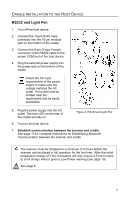
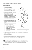
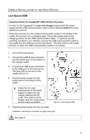
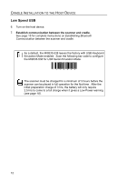
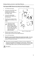
CRADLE INSTALLATION TO THE HOST DEVICE Low Speed USB Important Notes for VoyagerBT USB Interface Scanners In order for the VoyagerBT to scan and charge properly both the power supply and the USB communication cable must be attached before the host device is turned on. When the scanner is in the cradle and the power supply is connected to the cradle, the scanner is in a charging state. The power supply acts as the charging source not the USB communication cable. To perform normal scanning operations, it is critical to connect the USB communication cable to the cradle and the USB port on the host device. The blue LED on the cradle will turn on when the USB communication cable is connected. 1. Turn off the host device. 2. Connect the USB B type connector into the center jack on the bottom of the charger cradle. 3. Connect the USB A type connector to the USB port on the host device. The blue LED on the rear of the cradle will turn on. 4. Plug the power supply into the power jack on the bottom of the cradle. Check the AC input requirements of the power supply to make sure the voltage matches the AC outlet. The outlet must be located near the requirement and be easily accessible. Figure 8. Low Speed USB 5. Plug the power supply into the AC outlet. Installation instructions continued on page next page. See page 6. 11
-
 1
1 -
2
-
3
-
4
-
5
-
6
-
7
-
8
-
9
-
 10
10 -
 11
11 -
 12
12 -
 13
13 -
 14
14 -
 15
15 -
 16
16 -
 17
17 -
 18
18 -
 19
19 -
 20
20 -
21
-
22
-
23
-
24
-
25
-
26
-
27
-
28
-
29
-
30
-
31
-
32
-
33
-
34
-
35
-
36
-
37
-
38
-
39
-
40
-
41
-
42
-
43
-
44
-
45
-
46
-
47
-
48
-
49
-
50
-
51
-
52
-
53
-
54
-
55
-
56
-
57
-
58
-
59
-
60
 |
 |