Intel SBXD62 User Guide - Page 34
an Intel® Blade Server Chassis SBCE on Removing the Blade Server Bezel Assembly
 |
UPC - 735858185448
View all Intel SBXD62 manuals
Add to My Manuals
Save this manual to your list of manuals |
Page 34 highlights
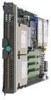
The following illustration shows how to install the second microprocessor on the system board for the blade server. Heat Sink Microprocessor 2 Microprocessor 1 and Heat Sink AF000446 To install an additional microprocessor, complete the following steps: 1. Read the safety information beginning on page 65 in Appendix C, "Safety Information" and "Installation Guidelines" on page 15. 2. Shut down the operating system, turn off the blade server, and remove the blade server from the Intel® Blade Server Chassis SBCE. See "Removing the Blade Server from an Intel® Blade Server Chassis SBCE" on page 17 for instructions. 3. Carefully lay the blade server on a flat, static-protective surface. 4. Open the blade server cover (see "Opening the Blade Server Cover" on page 18 for instructions). 5. Remove the bezel assembly (see "Removing the Blade Server Bezel Assembly" on page 19 for instructions). 6. Locate the microprocessor socket on the system board. 7. Remove the two screws that secure the heat-sink filler and then remove the filler from the microprocessor socket. 8. Install the microprocessor: a. Remove the protective cover, tape, or label from the surface of the microprocessor socket, if one is present. b. Touch the static-protective package that contains the new microprocessor to any unpainted metal surface on the blade server or any unpainted metal surface on any other grounded rack component in the rack you are installing the microprocessor in for at least 2 seconds; then, remove the microprocessor from the package. Important: Do not use any tools or sharp objects to lift the locking lever on the microprocessor socket. Doing so might result in permanent damage to the system board. c. Rotate the locking lever on the microprocessor socket from its closed and locked position until it stops or clicks in the fully open position (approximately a 135degree angle), as shown. 24 Intel® Server Compute Blade SBXD62 Installation and User's Guide
-
 1
1 -
2
-
3
-
4
-
5
-
6
-
7
-
8
-
9
-
10
-
11
-
12
-
13
-
14
-
15
-
16
-
17
-
18
-
19
-
20
-
21
-
22
-
23
-
24
-
25
-
26
-
27
-
28
-
 29
29 -
 30
30 -
 31
31 -
 32
32 -
 33
33 -
 34
34 -
 35
35 -
 36
36 -
 37
37 -
 38
38 -
 39
39 -
40
-
41
-
42
-
43
-
44
-
45
-
46
-
47
-
48
-
49
-
50
-
51
-
52
-
53
-
54
-
55
-
56
-
57
-
58
-
59
-
60
-
61
-
62
-
63
-
64
-
65
-
66
-
67
-
68
-
69
-
70
-
71
-
72
-
73
-
74
-
75
-
76
-
77
-
78
-
79
-
80
-
81
-
82
-
83
-
84
-
85
-
86
-
87
-
88
-
89
-
90
-
91
-
92
-
93
-
94
-
95
-
96
-
97
-
98
-
99
-
100
-
101
-
102
-
103
-
104
-
105
-
106
-
107
-
108
-
109
-
110
-
111
-
112
-
113
-
114
-
115
-
116
-
117
-
118
 |
 |
