JVC TK-AM200U TK-AM200 Dome CCTV Camera Instruction Manual (748KB)
JVC TK-AM200U - Active Movement Color Dome Camera Manual
 |
View all JVC TK-AM200U manuals
Add to My Manuals
Save this manual to your list of manuals |
JVC TK-AM200U manual content summary:
- JVC TK-AM200U | TK-AM200 Dome CCTV Camera Instruction Manual (748KB) - Page 1
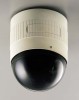
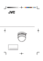
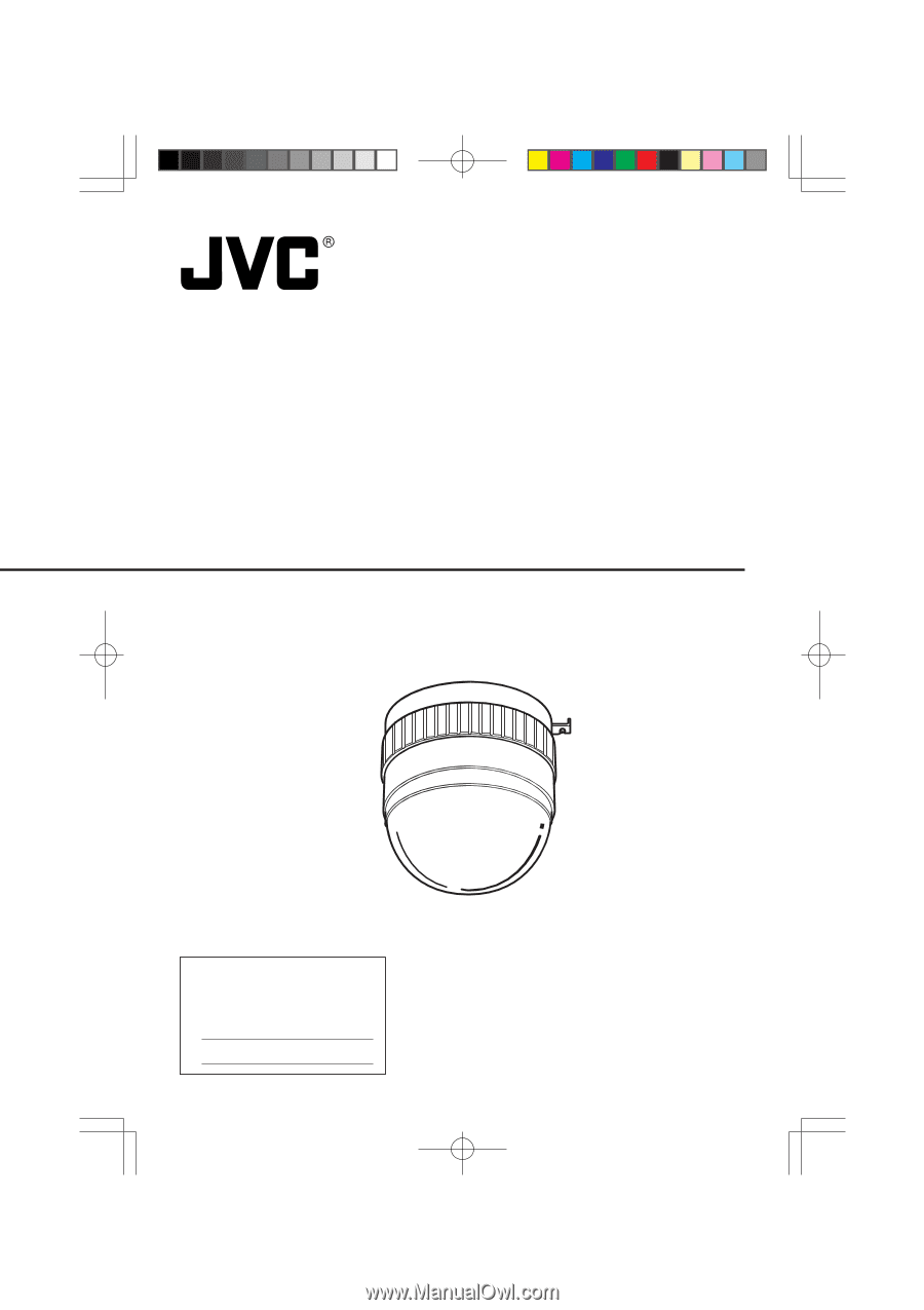
ACTIVE MOVEMENT VIDEO CAMERA TK-AM200 INSTRUCTIONS For Customer Use: Enter below the Serial No. which is located on the body. Retain this information for future reference. Model No. Serial No. TK-AM200 This instruction book is made from 100% recycled paper. SC96866-001 3 - JVC TK-AM200U | TK-AM200 Dome CCTV Camera Instruction Manual (748KB) - Page 2
Use only with a cart or stand recommended by the manufacturer, or sold with the appliance. Wall or shelf mounting should follow the manufacturer's instructions, and should use a mounting kit approved by the manufacturer. An appliance and cart combination should be S3126A moved with care. Quick stops - JVC TK-AM200U | TK-AM200 Dome CCTV Camera Instruction Manual (748KB) - Page 3
service personnel under the following conditions: a. When the power cord or plug is damaged or frayed. b. If liquid has been spilled into the appliance. c. If the appliance has been exposed to rain or water. d. If the appliance does not operate normally by following the operating instructions - JVC TK-AM200U | TK-AM200 Dome CCTV Camera Instruction Manual (748KB) - Page 4
to the presence of important operating and maintenance (servicing) instructions in the literature accompanying the appliance. This device complies with part 15 of the FCC Rules. Changes or modifications not approved by JVC - JVC TK-AM200U | TK-AM200 Dome CCTV Camera Instruction Manual (748KB) - Page 5
Thank you for purchasing this product. (These instructions are for TK-AM200U.) CONTENTS INTRODUCTION Features ...6 Safety Precautions ...6 Operating Precautions ...7 Controls, Connectors and Indicators ...8 Camera Body ...8 Ceiling Mount ...9 SYSTEM RM-P2580 System ...10 INSTALLATION Connections to - JVC TK-AM200U | TK-AM200 Dome CCTV Camera Instruction Manual (748KB) - Page 6
the video image at specified pre-set positions in the set order. Safety Precautions Installation of this unit requires expertise. Please contact your JVC dealer for details. Be sure to tighten the screws and nuts used for installation securely. Insufficient tightening could cause the unit to fall - JVC TK-AM200U | TK-AM200 Dome CCTV Camera Instruction Manual (748KB) - Page 7
grainy. This is not a malfunction. ● Use the ATW (auto-tracking white balance) mode when the camera is used under fluorescent lighting. If set to MANUAL, the correct white balance may not be accomplished. ● When this camera is used in the ATW (auto-tracking white balance) mode, the recorded colors - JVC TK-AM200U | TK-AM200 Dome CCTV Camera Instruction Manual (748KB) - Page 8
signal cable, the power cable, the control signal cable, and the alarm input signal cable. ( See page 12.) Camera body mounting guides (×3) To be inserted into the guide holes 16 of the ceiling mount. 8 Camera body clamp Fix the camera body to the ceiling mount by fastening the ceiling mount - JVC TK-AM200U | TK-AM200 Dome CCTV Camera Instruction Manual (748KB) - Page 9
on page 14.) 16 Guide holes for mounting camera (×3) Guide holes for mounting the camera body. The camera body mounting guides 7 are inserted into on the camera body with this protrusion. 14 FOR SERVICE connector Exclusively for service purposes. 20 Drop prevention wire hook Attach this wire to - JVC TK-AM200U | TK-AM200 Dome CCTV Camera Instruction Manual (748KB) - Page 10
Camera 1 Camera ID: 01 Termination: OFF Control signal cable Video signal cable Power cable AC24V Camera TK-AM200 Camera 2 Camera ID: 02 Termination: OFF AC24V Camera TK-AM200 Camera 8 Camera ID: 08 Termination: ON MONITOR AC24V CAM SW Time lapse VCR OUT REC STOP/EJECT REC CHECK VIDEO CASSETTE - JVC TK-AM200U | TK-AM200 Dome CCTV Camera Instruction Manual (748KB) - Page 11
: Set to the RS-422A/RS-485 side. ●Turn OFF the power supply to all equipment to be used before making connections. ●Carefully read the Instruction Manual for each piece of equipment to be used before making connections. ●For the appropriate connection cables and the length of these, carefully read - JVC TK-AM200U | TK-AM200 Dome CCTV Camera Instruction Manual (748KB) - Page 12
INSTALLATION Connections to Terminal Board Remove the terminal board cover by flipping it up while pushing its top to the left. Turn OFF the power supply to all equipment to be used before making connections. Connections to Terminal Board Remove the terminal board cover and connect the video signal - JVC TK-AM200U | TK-AM200 Dome CCTV Camera Instruction Manual (748KB) - Page 13
INSTALLATION Camera Settings Set the switches on the side of the camera in accordance with the system or equipment to be connected to. Always turn OFF the power before setting the switches. 1. Press. 2. Switch cover System setting switches Control signal selector switch Camera ID setting switch - JVC TK-AM200U | TK-AM200 Dome CCTV Camera Instruction Manual (748KB) - Page 14
3. Set system setting switches. Switches ON ON 1 1 2 3 4 5 6 7 8 Switch numbers OFF 1 ● Switch 1, 2: System connection selector switch Set the system connection selector switches (Switch 1, 2) in accordance with the equipment that the camera body is to be connected to. Connecting equipment - JVC TK-AM200U | TK-AM200 Dome CCTV Camera Instruction Manual (748KB) - Page 15
terminal board through the hole in the ceiling mount and attach it to the camera body. 1) Slide the tab on the terminal board into the guide on the camera. When the terminal board is moved in the direction of the arrow, it is secured to the camera. 2) Connect the connector cable - JVC TK-AM200U | TK-AM200 Dome CCTV Camera Instruction Manual (748KB) - Page 16
5. Positioning alignment protrusion A Camera clamping screw 5. Camera clamp B Mount the camera body. 1) Ensure that the camera clamping screw on the ceiling mount is loosened. 2) Align the ceiling mount's positioning alignment protrusion (A in the illustration on the left) with the camera clamp - JVC TK-AM200U | TK-AM200 Dome CCTV Camera Instruction Manual (748KB) - Page 17
-in menus can be called up and set from the remote control unit. This function is explained on this page. (For details, refer to the Instruction Manual for the remote control unit.) MENU SET button button REMOTE CONTROL UNIT RM-P2580 CAMERA POWER SET ALARM KEY LOCK AUTO F-1 F-2 F-3 POSITION Power - JVC TK-AM200U | TK-AM200 Dome CCTV Camera Instruction Manual (748KB) - Page 18
Menu Screen Flow The menu screen flow is as follows. For details, see the pages referred to. See page 20. Normal screen C A M E R A MO D E S E L E C T V . PHASE 127 P O S . T E X T L OC . UP - L A LM . TEX T S I Z E DOU B L E B LC ED I T 1 . . B LC ED I T 2 . . See page 21. SE TUP POS I T I ON SE T - JVC TK-AM200U | TK-AM200 Dome CCTV Camera Instruction Manual (748KB) - Page 19
Changing Camera Settings Using the RM-P2580 CAMERA MODE SELECT Screen Used for setting functions separately for each camera. Item V. PHASE Function Used to adjust and align the vertical phase of the camera body with other cameras operating in the Line Lock (LL) mode. Adjust while viewing the monitor - JVC TK-AM200U | TK-AM200 Dome CCTV Camera Instruction Manual (748KB) - Page 20
CAMERA VIDEO ADJUST Screen Used for setting functions related to the video image of each camera. Item AGC MODE Function Sets the maximum gain of the AGC (Automatic Gain Control). • Set to OFF when the AGC function is not used. • Set to 20 dB when illumination is particularly dim. Used when the - JVC TK-AM200U | TK-AM200 Dome CCTV Camera Instruction Manual (748KB) - Page 21
screen is effective and the value resulting from the AWC adjustment is stored in the camera body. However, when the positions set by "ATW" or "MANUAL" are selected again, the image returns from the setting determined by the value resulting from the AWC adjustment to the setting values of "ATW" or - JVC TK-AM200U | TK-AM200 Dome CCTV Camera Instruction Manual (748KB) - Page 22
To stop the light metering area display, press the MENU button. W. BALANCE Used for selecting the white balance adjustment func- tion. MANUAL: Selects the manual adjustment mode. (Adjustment is made in the following items RB GAIN and MG GAIN.) ATW: Automatic color temperature adjustment mode. AWC - JVC TK-AM200U | TK-AM200 Dome CCTV Camera Instruction Manual (748KB) - Page 23
the RM-P2580, this setting becomes invalid. The mode becomes the ALARM priority mode. MAKE BREAK MAKE MODE HOME POS 1 to POS 15 ALARM MANUAL POS 1 ALARM FACTORY SETTINGS Screen Used for returning all settings to the default values. Item FACTORY SETTINGS Function Used to return menu settings to - JVC TK-AM200U | TK-AM200 Dome CCTV Camera Instruction Manual (748KB) - Page 24
BLC EDIT Screen This is a screen for changing the position of the light metering area used for backlight compensation. There are two types of screens on which the light metering area can be changed. (BLC EDIT 1 and BLC EDIT 2) C A M E R A MO D E S E L E C T V . PHASE 127 P O S . T E X T L OC . UP - - JVC TK-AM200U | TK-AM200 Dome CCTV Camera Instruction Manual (748KB) - Page 25
Select the camera whose text should be set. Use the CAMERA button → Numeric key → ENTER button to select the camera. For details, see the instruction manual for the RM-P2580. 1. Select the CAMERA TEXT.. item on the TEXT EDIT screen, and then press the SET button. ● The CAMERA TEXT screen appears - JVC TK-AM200U | TK-AM200 Dome CCTV Camera Instruction Manual (748KB) - Page 26
position for which position title text should be set. Use the POSITION button → Numeric key → ENTER button to select the position. For details, see the instruction manual for the RM-P2580. Use the ZOOM (TELE) or ZOOM (WIDE) button to select the position in the text input area. The position moves to - JVC TK-AM200U | TK-AM200 Dome CCTV Camera Instruction Manual (748KB) - Page 27
Changing Camera Settings Using the RM-P2580 AUTO PAN Setting AUTO PAN is a function that automatically swings the camera horizontally in a panning movement. Select this setting to observe the range between two points. (Set for each camera.) MENU SET button button REMOTE CONTROL UNIT RM-P2580 CAMERA - JVC TK-AM200U | TK-AM200 Dome CCTV Camera Instruction Manual (748KB) - Page 28
4. R E T U RN P OS I T I ON SE T Use the PAN/TILT control lever to align the cursor (>) with the RETURN POSITION SET item. When the SET button is pressed, the RETURN POSITION SET screen is displayed. ● Adjust the angle of view at the return position using the PAN/TILT control lever. Memo: RETURN - JVC TK-AM200U | TK-AM200 Dome CCTV Camera Instruction Manual (748KB) - Page 29
I NGS . . Use the CAMERA button → Numeric key → ENTER button to select the camera to be set for auto pan. For details, see the instruction manual for the RM-P2580. 1. Camera SETUP screen AUTO PATROL screen AU T O PA T RO L P A T RO L 1 HOM E P A T RO L 2 PO S 1 P A T RO L 3 PO S 2 P A T RO L 4 PO - JVC TK-AM200U | TK-AM200 Dome CCTV Camera Instruction Manual (748KB) - Page 30
The next AUTO PATROL screen AU T O PA T RO L P A T RO L 9 PO S 8 P A T RO L 1 0 PO S 9 P A T RO L 1 1 PO S 1 0 P A T RO L 1 2 PO S 1 1 P A T RO L 1 3 PO S 1 2 P A T RO L 1 4 PO S 1 3 P A T RO L 1 5 PO S 1 4 P A T RO L 1 6 PO S 1 5 F WD / BW D > Z O OM 2. 1 1 1 1 1 1 1 1 0 0 0 0 0 0 0 0 s s s s s - JVC TK-AM200U | TK-AM200 Dome CCTV Camera Instruction Manual (748KB) - Page 31
position can be invoked from which surveillance is then conducted. The camera can be set so that the PANIC ALARM operation overrides manual operation, AUTO PATROL operation and AUTO PATROL operation by terminating these. By installing a switch near the camera, a single press in an emergency - JVC TK-AM200U | TK-AM200 Dome CCTV Camera Instruction Manual (748KB) - Page 32
Memo: Minimum 70 ms or more is required for the camera body to detect the switched condition of the contact. Example: In the case of MAKE SHORT OPEN Alarm detection Alarm detection not guaranteed 70 ms or more 70 ms 3. Setting of Alarm Condition Duration (DURATION) Set how long the alarm - JVC TK-AM200U | TK-AM200 Dome CCTV Camera Instruction Manual (748KB) - Page 33
speed: 2°/s, 4°/s, 6°/s, 12°/s, 20°/s, 40°/s, 60°/s, 80°/s (in MANUAL mode) 120°/s (Preset maximum) General Power requirement: AC 24V 50/60Hz, ) Mass: 0.8 kg (including ceiling mount) Accessories: Instructions ×1 Warranty Card ×1 Service Information Card × 1 Ceiling Mount ×1 Terminal Board ×1 - JVC TK-AM200U | TK-AM200 Dome CCTV Camera Instruction Manual (748KB) - Page 34
External dimensions [Unit: mm] ø75 (26) Terminal board ing 83.5 Mo unt ø hole 75 46 Mounting hole in ceiling 446 ø110 Camera body 83.5 Ceiling mount • Design and specifications are subject to change without notice. 135 1 ø4 .5 ø6 5 35 - JVC TK-AM200U | TK-AM200 Dome CCTV Camera Instruction Manual (748KB) - Page 35
TK-AM200 ACTIVE MOVEMENT VIDEO CAMERA VICTOR COMPANY OF JAPAN, LIMITED ® ® is a registered trademark owned by VICTOR COMPANY OF JAPAN, LTD. is a registered trademark in Japan, the U.S.A., the U.K. and many other countries. © 1999 VICTOR COMPANY OF JAPAN, LIMITED Printed in Japan SC96866-001
-
 1
1 -
 2
2 -
 3
3 -
 4
4 -
 5
5 -
 6
6 -
 7
7 -
8
-
9
-
10
-
11
-
12
-
13
-
14
-
15
-
16
-
17
-
18
-
19
-
20
-
21
-
22
-
23
-
24
-
25
-
26
-
27
-
28
-
29
-
30
-
31
-
32
-
33
-
34
-
35
 |
 |
3
TK-AM200
INSTRUCTIONS
For Customer Use:
Enter below the Serial No. which is
located on the body. Retain this
information for future reference.
Model No.
TK-AM200
Serial No.
This instruction book is made from
100% recycled paper.
ACTIVE MOVEMENT VIDEO CAMERA
SC96866-001