JVC TK-AM200U TK-AM200 Dome CCTV Camera Instruction Manual (748KB) - Page 24
JVC TK-AM200U - Active Movement Color Dome Camera Manual
 |
View all JVC TK-AM200U manuals
Add to My Manuals
Save this manual to your list of manuals |
Page 24 highlights
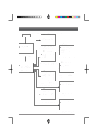
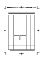
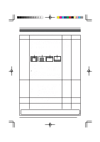
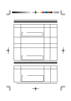
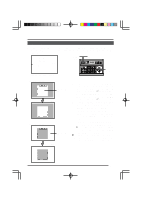
BLC EDIT Screen This is a screen for changing the position of the light metering area used for backlight compensation. There are two types of screens on which the light metering area can be changed. (BLC EDIT 1 and BLC EDIT 2) C A M E R A MO D E S E L E C T V . PHASE 127 P O S . T E X T L OC . UP - L A LM . TEX T S I Z E DOU B L E B LC ED I T 1 . . B LC ED I T 2 . . MENU button SETUP POWER SET ALARM KEY LOCK MENU SET button REMOTE CONTROL UNIT RM-P2580 CAMERA POSITION AUTO F-1 F-2 F-3 LENS SPEED CAMERA/POSITION PAN/TILT POSITION 1 OPEN 2 5 8 0 /HOME 3 6 9 ENTER CAMERA CLOSE IRIS 4 7 CLEAR OPTION 1 OPTION 2 NEAR FOCUS AF FAR AUTO PAN AUTO PATROL WIDE ZOOM TELE PAN/TILT control lever CAMERA MODE SELECT screen RM-P2580 BLC EDIT 1 screen 1. Light metering area SET button Select BLC EDIT 1 on the CAMERA MODE SELECT screen. When the SET button is pressed, the BLC EDIT 1 screen is displayed. ( See page 20.) When BLC EDIT 2 is selected and the SET button is pressed, the BLC EDIT 2 screen is displayed. ( See page 20.) Press the SET button to select the edges of the light metering area to be set. (Left/Up → Right/Down → Left/Down ...) Press the PAN/TILT control lever up, down, left, or right to enlarge or decrease the area occupied by the light metering area. 2. 3. 4. BLC EDIT 2 screen Light metering area When done with setting of the light metering area, press the MENU button. ● The set light metering area is retained in memory, and the CAMERA MODE SELECT screen returns. To use the set light metering area, set the BLC MODE item on the VIDEO ADJUST FOR POSI screen to EDIT 1 or EDIT 2. SET button 25
-
 1
1 -
2
-
3
-
4
-
5
-
6
-
7
-
8
-
9
-
10
-
11
-
12
-
13
-
14
-
15
-
16
-
17
-
18
-
 19
19 -
 20
20 -
 21
21 -
 22
22 -
 23
23 -
 24
24 -
 25
25 -
 26
26 -
 27
27 -
 28
28 -
 29
29 -
30
-
31
-
32
-
33
-
34
-
35
 |
 |
