JVC TK-AM200U TK-AM200 Dome CCTV Camera Instruction Manual (748KB) - Page 14
JVC TK-AM200U - Active Movement Color Dome Camera Manual
 |
View all JVC TK-AM200U manuals
Add to My Manuals
Save this manual to your list of manuals |
Page 14 highlights
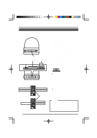
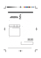
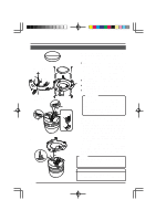
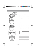
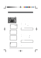
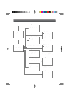
3. Set system setting switches. Switches ON ON 1 1 2 3 4 5 6 7 8 Switch numbers OFF 1 ● Switch 1, 2: System connection selector switch Set the system connection selector switches (Switch 1, 2) in accordance with the equipment that the camera body is to be connected to. Connecting equipment Switch 1 Switch 2 ● Switch 4: Synchronization signal selector switch Switches the synchronization method of the camera image. OFF: Internal synchronization (INT) ON: The camera's vertical synchronization is matched with the frequency of the AC 24V line power supply. When switching between multiple cameras using a switcher, selecting this mode and adjusting the vertical phase can reduce the monitor sync disturbances occurring when the camera image is switched. (This cannot be used in regions where the power frequency is 50 Hz.) ● Switches 5, 6, 7, 8 These switches are not used. (Set them to OFF.) RM-P2580 ON OFF Memo: Switch 1 and 2 are used to specify the form of the control signal cable connection between the remote control unit and the camera and the communication protocol. Switch 1 (Initial setting: OFF) OFF: POINT TO POINT ON: MULTIDROP Switch 2: (Initial setting: OFF) OFF: DUPLEX (two-way data transmission) ON: SIMPLEX (one-way data transmission) 4. Memo: Double figures Single figures If the camera ID numbers of cameras connect to the RM-P2580 are duplicated, the system will not work correctly. 5. When setting of the switches is completed, close the cover over the setting switches again. 456 456 ● Switch 3: Termination ON/OFF switch This is a termination ON/OFF switch between the "RX+" and "RX-" control signal connection terminals. ON: The "RX+" to "RX-" route is terminated by a 110Ω resistor. OFF: The RX+ to RX- route is not terminated. (Initial setting: OFF) In a system using the Remote Control Unit RM-P2580, set this to "ON" only on the camera placed at the end of the control signal cable. Set to OFF on all other cameras. 78 78 Camera ID setting switches Camera ID setting is only performed when the system connection selector switches (Switch 1 and 2) are set to "RMP2580". The camera ID number is a number to identify each of the cameras connect to the RM-P2580. The camera ID number should be the same as the number of the RM-P2580 VIDEO INPUT terminal to which the camera is connected. Example: The camera connected to VIDEO "0" "1" INPUT 1 is set to "01" as shown 01 901 9 on the right. 23 23 15
-
 1
1 -
2
-
3
-
4
-
5
-
6
-
7
-
8
-
 9
9 -
 10
10 -
 11
11 -
 12
12 -
 13
13 -
 14
14 -
 15
15 -
 16
16 -
 17
17 -
 18
18 -
 19
19 -
20
-
21
-
22
-
23
-
24
-
25
-
26
-
27
-
28
-
29
-
30
-
31
-
32
-
33
-
34
-
35
 |
 |
