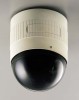
JVC TK-AM200U TK-AM200 Dome CCTV Camera Instruction Manual (748KB) - Page 16
JVC TK-AM200U - Active Movement Color Dome Camera Manual
 |
View all JVC TK-AM200U manuals
Add to My Manuals
Save this manual to your list of manuals |
Page 16 highlights
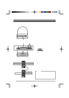
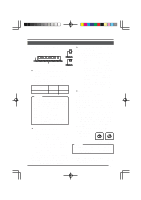
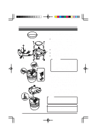
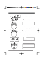
5. Positioning alignment protrusion A Camera clamping screw 5. Camera clamp B Mount the camera body. 1) Ensure that the camera clamping screw on the ceiling mount is loosened. 2) Align the ceiling mount's positioning alignment protrusion (A in the illustration on the left) with the camera clamp (B in the illustration on the left) position on the camera body and press the camera body straight against the mount. CAUTION: Exercise caution so as not to pinch the drop prevention wire and the connected cables. 3) Rotate the camera body clockwise as far as it will go. At this point, check that the camera body clamp is located on the camera clamping screw on the ceiling mount. 4) Tighten the camera clamping screw. Changing the position of the mounted camera body 1) Slightly loosen the camera clamping screw. By turning the camera body counterclockwise, the position of the m o u n t e d c a m e ra b o d y c a n b e changed within a range of approximately 40 degrees (approximately 20 degrees to the left and right). Camera clamp Camera clamping screw Ceiling mount Memo: Loosening the camera clamping screw too much will cause the camera body to come off the ceiling mount. Camera (Tighten.) body Camera clamping screw (Slightly loosen) 2) After the position for the camera body is decided, tighten the camera clamping screw. CAUTION Be sure to tighten the camera clamping screw fully. Otherwise the camera body may vibrate or drop from the ceiling. To dismount the camera from the ceiling, perform steps 3. to 5. in reverse order. 17
-
 1
1 -
2
-
3
-
4
-
5
-
6
-
7
-
8
-
9
-
10
-
 11
11 -
 12
12 -
 13
13 -
 14
14 -
 15
15 -
 16
16 -
 17
17 -
 18
18 -
 19
19 -
 20
20 -
 21
21 -
22
-
23
-
24
-
25
-
26
-
27
-
28
-
29
-
30
-
31
-
32
-
33
-
34
-
35
 |
 |
