JVC TK-AM200U TK-AM200 Dome CCTV Camera Instruction Manual (748KB) - Page 10
JVC TK-AM200U - Active Movement Color Dome Camera Manual
 |
View all JVC TK-AM200U manuals
Add to My Manuals
Save this manual to your list of manuals |
Page 10 highlights
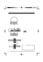
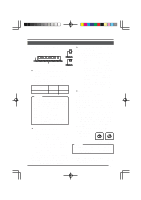
SYSTEM RM-P2580 System System with up to 8 cameras (Sixteen position settings available for each camera.) Camera TK-AM200 Camera 1 Camera ID: 01 Termination: OFF Control signal cable Video signal cable Power cable AC24V Camera TK-AM200 Camera 2 Camera ID: 02 Termination: OFF AC24V Camera TK-AM200 Camera 8 Camera ID: 08 Termination: ON MONITOR AC24V CAM SW Time lapse VCR OUT REC STOP/EJECT REC CHECK VIDEO CASSETTE RECORDER REVERSE PAUSE/ STILL PLAY COUNT/ CLOCK SHIFT/TRACKING MENU RESET /CANCEL REW FF TIME MODE TIMER REC SET/V.LOCK AL/PL RESET SR-L910 OPERATE OPE. LOCK VIDEO IN TO CAMERA RX+ RX- | RX { TX+ {TX- | CAMERA SW COM COM 1 2 3 4 5 6 7 8 MONITOR SERIAL-2 MONITOR MONITOR OUTPUT OUTPUT 1 2 TO CAMERA DATA I / O UNIT CAMERA COM 9/1 10/2 11/3 12/4 13/5 14/6 15/7 16/8 COM AUTO ALARM COM SW COM SERIAL-1 POWER Remote Control Unit RM-P2580 ON OFF 1 2 3 4 VIDEO INPUT 5 6 7 8 AC 'INPUT 1 2 3 4 5 6 7 8 MONITOR OUTPUT 2 ON 1 2 3 4 5 VIDEO OUTPUT 6 7 8 MONITOR OUTPUT 1 Memo: • When operating a system using the RM-P2580, several cameras (up to 8) can be connected and used on one control signal cable. Consequently, an incorrect switch setting on just a single camera will cause the entire system to work incorrectly. MONITOR screen (example showing camera ID as "05") • Confirm switch settings on the screen as follows. q Confirm that the image from the camera to be checked is displayed on the monitor. w Turn OFF and then ON the AC 24 V power to the camera to be checked. IN I T I AL e The camera begins the initial operation and characters similar to those shown in the illustration on the right appear on the monitor screen. r Confirm that "DUPLEX" and "ID" are displayed P RO T OCO L D U P L E X I D - 0 5 and that the ID number is the correct number (the number should be the same as the number of the VIDEO INPUT terminal to which the camera is "DUPLEX" should The number shown in connected on the rear panel of the RM-P2580). the □□ part of ID-□□ be displayed. should be correct. t If wrong, set the camera ID again. 10
-
 1
1 -
2
-
3
-
4
-
 5
5 -
 6
6 -
 7
7 -
 8
8 -
 9
9 -
 10
10 -
 11
11 -
 12
12 -
 13
13 -
 14
14 -
 15
15 -
16
-
17
-
18
-
19
-
20
-
21
-
22
-
23
-
24
-
25
-
26
-
27
-
28
-
29
-
30
-
31
-
32
-
33
-
34
-
35
 |
 |
