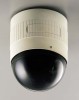
JVC TK-AM200U TK-AM200 Dome CCTV Camera Instruction Manual (748KB) - Page 8
JVC TK-AM200U - Active Movement Color Dome Camera Manual
 |
View all JVC TK-AM200U manuals
Add to My Manuals
Save this manual to your list of manuals |
Page 8 highlights
INTRODUCTION Controls, Connectors and Indicators Camera Body (With terminal board in attached condition) (Side view) 7 6 4 3 5 0 7 9 2 1 $ 8 1 7 7 # @ ! Terminal board To connect the coaxial cable used as the video signal cable, the power cable, the control signal cable, and the alarm input signal cable. ( See page 12.) Camera body mounting guides (×3) To be inserted into the guide holes 16 of the ceiling mount. 8 Camera body clamp Fix the camera body to the ceiling mount by fastening the ceiling mount's camera clamping screw 18 to this clamp. 2 Video output terminal Outputs composite video signals (1V(p-p), output impedance 75 Ω). 9 Drop prevention wire hook Attach the drop prevention wire 20 from the ceiling mount to this hook. 3 Control signal connection terminals Terminals for inputting signals with electrical characteristics conforming to the EIA/TIA RS-422A or RS-485 standard. 10 Switch cover Open this cover to use the setting switches. The cover can be opened by pushing the cover edge in the direction of the arrow. 4 5 AC 24 V input terminal To input AC 24 V power. Panic alarm signal input terminal Terminal for inputting the panic alarm signal. Settings concerning the panic alarm signal should be made using the PANIC ALARM SET screen. ( See pages 24 and 32.) 11 Control signal selector switch (RS-422A/RS-485, RS-232C) Switches the communication mode of the control signal terminal 3 . • When connected to the RM-P2580, set to the RS-422A/RS-485 side. • When connected to a personal computer, etc. set to the RS-232C side. 6 Terminal board cover Protects the cable connection terminals from dirt, etc. 8
-
 1
1 -
2
-
 3
3 -
 4
4 -
 5
5 -
 6
6 -
 7
7 -
 8
8 -
 9
9 -
 10
10 -
 11
11 -
 12
12 -
 13
13 -
14
-
15
-
16
-
17
-
18
-
19
-
20
-
21
-
22
-
23
-
24
-
25
-
26
-
27
-
28
-
29
-
30
-
31
-
32
-
33
-
34
-
35
 |
 |
