JVC TK-AM200U TK-AM200 Dome CCTV Camera Instruction Manual (748KB) - Page 20
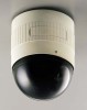
JVC TK-AM200U - Active Movement Color Dome Camera Manual
 |
View all JVC TK-AM200U manuals
Add to My Manuals
Save this manual to your list of manuals |
Page 20 highlights
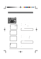
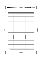
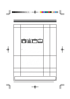
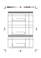
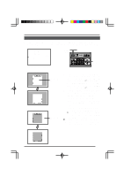
CAMERA VIDEO ADJUST Screen Used for setting functions related to the video image of each camera. Item AGC MODE Function Sets the maximum gain of the AGC (Automatic Gain Control). • Set to OFF when the AGC function is not used. • Set to 20 dB when illumination is particularly dim. Used when the brightness is still insufficient even if the AGC MODE is set at 20 dB. ON: Gain level is increased. OFF: Gain level is not increased. ∗ When SUPER AGC is ON; • Dark areas of the screen may appear grainy. • Gain will be set according to the setting of the SUPER AGC with no relation to the AGC MODE setting. Used to set the electronic shutter speed for each camera. To reduce flickering caused by fluorescent lighting, set the electronic shutter speed to 1/100 in areas where the commercial power supply frequency is 50 Hz, and to 1/60 in areas where the frequency is 60 Hz. Contour compensation function that enhances the sharpness of the monitor screen. LOW: Low contour enhancement HIGH: High contour enhancement Sets the exposure detection as a ratio of the average value and the peak value. • AVERAGE value large: Increase the AVERAGE value when portions other than the highlighted areas of the screen are dark and look corrupted. (Ex. 10/0) • PEAK value large: Increase the PEAK value when halation occurs in the highlighted areas of the screen. (Ex. 5/5) Variable range OFF 10 dB 20 dB Factory setting 10 dB SUPER AGC ON OFF OFF SHUTTER SPEED 1/60 1/100 1/60 ENHANCE LOW HIGH HIGH AV/PEAK 10/0 9/1 8/2 7/3 6/4 5/5 8/2 21
-
 1
1 -
2
-
3
-
4
-
5
-
6
-
7
-
8
-
9
-
10
-
11
-
12
-
13
-
14
-
 15
15 -
 16
16 -
 17
17 -
 18
18 -
 19
19 -
 20
20 -
 21
21 -
 22
22 -
 23
23 -
 24
24 -
 25
25 -
26
-
27
-
28
-
29
-
30
-
31
-
32
-
33
-
34
-
35
 |
 |
