JVC TK-AM200U TK-AM200 Dome CCTV Camera Instruction Manual (748KB) - Page 18
JVC TK-AM200U - Active Movement Color Dome Camera Manual
 |
View all JVC TK-AM200U manuals
Add to My Manuals
Save this manual to your list of manuals |
Page 18 highlights
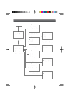
Menu Screen Flow The menu screen flow is as follows. For details, see the pages referred to. See page 20. Normal screen C A M E R A MO D E S E L E C T V . PHASE 127 P O S . T E X T L OC . UP - L A LM . TEX T S I Z E DOU B L E B LC ED I T 1 . . B LC ED I T 2 . . See page 21. SE TUP POS I T I ON SE T U P . . C AME R A . . CON T RO L UN I T . . CAMERA MODE SELECT screen (Used for setting functions separately for each camera.) See page 23. C AME R A V I D EO A D J U S T A G C MO D E 10dB S U P E R A GC OF F SHUT T ER S PEED 1 / 60 ENHANCE H I GH AV / PEAK 8 / 2 CO L OR L E V E L 5 AWC A D J U S T . . SETUP screen from the remote control V I DEO A D J US T B L C MO D E W . BA L ANCE RB GA I N MG G A I N F OR PO S I OF F A TW 186 192 CAMERA VIDEO ADJUST screen (Used for settings functions related to the video image of each camera.) See pages 26 to 27. TEXT ED I T C AME R A T E X T . . POS I T I ON T E X T . . SE TUP C A M E R A MO D E S E L E C T . . C AME R A V I D EO A D J U S T . . V I DEO A D J FOR POS I . . TEXT ED I T . . A U TO P A T RO L S E T . . AU TO PAN SE T . . P A N I C A L A RM S E T . . F A C T OR Y S E T T I NGS . . VIDEO ADJUST FOR POSI screen (Used for setting functions related to the image of each position.) See page 30. AU T O PA T RO L P A T RO L 1 HOM E P A T RO L 2 PO S 1 P A T RO L 3 PO S 2 P A T RO L 4 PO S 3 P A T RO L 5 PO S 4 P A T RO L 6 PO S 5 P A T RO L 7 PO S 6 P A T RO L 8 PO S 7 F WD / BW D > Z O OM 1 1 1 1 1 1 1 1 0 0 0 0 0 0 0 0 s s s s s s s s Camera SETUP screen TEXT EDIT screen (Used for setting and editing character strings superimposed on the screen.) See page 28. AU T O P AN S E T S T AR T POS I T I ON SE T . . RE TURN POS I T I ON S E T . . AUTO PATROL screen (Used for setting the auto patrol function for automatic sequential movement for each camera.) See page 24. PAN DURA T PO L AR POS I T MO D E I I I I C A L ARM ON TY ON SET 10s MA K E POS 1 A L A RM AUTO PAN SET screen (Used for settings related to auto panning.) See page 24. PANIC ALARM SET screen (Used for settings related to the panic alarm input.) F A C T O R Y S E T T I NGS F A C T OR Y S E T T I NGS NO FACTORY SETTINGS screen (For returning all settings to the default values.) 19
-
 1
1 -
2
-
3
-
4
-
5
-
6
-
7
-
8
-
9
-
10
-
11
-
12
-
 13
13 -
 14
14 -
 15
15 -
 16
16 -
 17
17 -
 18
18 -
 19
19 -
 20
20 -
 21
21 -
 22
22 -
 23
23 -
24
-
25
-
26
-
27
-
28
-
29
-
30
-
31
-
32
-
33
-
34
-
35
 |
 |
