JVC TK-AM200U TK-AM200 Dome CCTV Camera Instruction Manual (748KB) - Page 23
JVC TK-AM200U - Active Movement Color Dome Camera Manual
 |
View all JVC TK-AM200U manuals
Add to My Manuals
Save this manual to your list of manuals |
Page 23 highlights
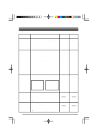
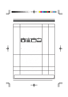
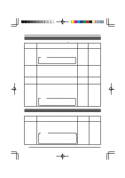
Changing Camera Settings Using the RM-P2580 PANIC ALARM SET Screen Used for settings related to the panic alarm input. ( Item DURATION Function See "PANIC ALARM" on page 32.) Variable Factory range setting 5, 6, 7, 8, 9, 10, 15, 20, 25, 30, 60 s, SERIES 10 s Sets the duration of the alarm mode operation when alarm signal is input. When set to SERIES, alarm mode operation continues. Note: When used in a system with the RM-P2580, this setting becomes invalid. Make the setting using the RM-P2580 ALARM TIME option. POLARITY POSITION Sets the polarity of the alarm input. MAKE: Alarm condition generated when MAKE connected. BREAK: Alarm condition generated when BREAK connected. Sets the camera position at the time of alarm input. Sets whether or not manual operation should be accepted during alarm operation. ALARM: Manual operation not accepted during alarm operation. MANUAL: Manual operation is accepted also during alarm operation. Note: When used in a system with the RM-P2580, this setting becomes invalid. The mode becomes the ALARM priority mode. MAKE BREAK MAKE MODE HOME POS 1 to POS 15 ALARM MANUAL POS 1 ALARM FACTORY SETTINGS Screen Used for returning all settings to the default values. Item FACTORY SETTINGS Function Used to return menu settings to the factory settings. YES: Returns settings to the factory settings. NO: Settings are not returned to the factory settings. Memo: When YES is selected and the SET button is pressed, after "EXECUTING" has been displayed for about 10 seconds on the screen, "DATA CLEARED" is shown for about 3 seconds. Do not turn off the power during this interval. Variable range YES NO Factory setting NO 24
-
 1
1 -
2
-
3
-
4
-
5
-
6
-
7
-
8
-
9
-
10
-
11
-
12
-
13
-
14
-
15
-
16
-
17
-
 18
18 -
 19
19 -
 20
20 -
 21
21 -
 22
22 -
 23
23 -
 24
24 -
 25
25 -
 26
26 -
 27
27 -
 28
28 -
29
-
30
-
31
-
32
-
33
-
34
-
35
 |
 |
