Kenmore 7808 Use and Care Guide - Page 9
path in Plan Vent System.
 |
View all Kenmore 7808 manuals
Add to My Manuals
Save this manual to your list of manuals |
Page 9 highlights
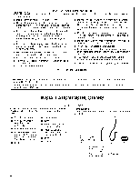
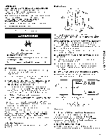
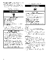
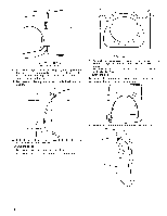
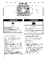
A B A. Standard rear offset exhaust installation B. Rear exhaust installation to right side (Part Number 8212504) or left side (Part Numbers 8544761 and 8212504). C D C. Bottom exhaust installation D. Over-the-top installation (alsoavailable with one offset elbow) NOTE: The following kits for alternate installations are available for purchase. For further information, please call 1-800-4-MY-HOME _ (1-800-469-4663). • Rear exhaust installation to right side: Part Number 8212504 • Rear exhaust installation to left side: Part Numbers 8544761 and 8212504 • Bottom exhaust installation: Part Number 8212503 • Over-the-top installation: Part Number 26-49900 Special provisions for mobile home installations The exhaust vent must be securely fastened to a noncombustible portion of the mobile home structure and must not terminate beneath the mobile home. Terminate the exhaust vent outside. Determine vent path • Select the route that will provide the straightest and most direct path outdoors. • Plan the installation to use the fewest number of elbows and turns. • When using elbows or making turns, allow as much room as possible. • Bend vent gradually to avoid kinking. • Usethe fewest 900 turns possible. Determine vent length and elbows needed for best drying performance • Use the following Vent system chart to determine type of vent material and hood combinations acceptable to use. NOTE: Do not use vent runs longer than those specified in the Vent system chart. Exhaust systems longer than those specified will: • Shorten the life of the dryer. • Reduce performance, resulting in longer drying times and increased energy usage. The Vent system chart provides venting requirements that will help to achieve the best drying performance. Vent system chart NOTE: Bottom exhaust performance is equivalent to adding two elbows. To determine maximum exhaust length, add two elbows to the chart. NOTE: Performance of rear exhaust to either side of the dryer is equivalent to adding one elbow. To determine maximum exhaust length, add one elbow to the chart. Number of 90 ° turns or elbows Type of vent Box or Louvered hoods Angled hoods 0 Rigid metal 200 ft (61 m) 185 ft (56.4 m) Flexible metal 100 ft (30.5 m) 93 ft (28.2 m) 1 Rigid metal 190 ft (58 m) 175 ft (53.3 m) Flexible metal 95 ft (29 m) 88 ft (26.7 m) 2 Rigid metal 180 ft (55 m) 165 ft (50.3 m) Flexible metal 90 ft (27.4 m) 83 ft (25.1 m) 3 Rigid metal 170 ft (51.8 m) 155 ft (47.2 m) Flexible metal 85 ft (26 m) 78 ft (23.6 m) 4 Rigid metal 160 ft (48.8 m) 145 ft (44.2 m) Flexible metal 80 ft (24.4 m) 73 ft (22.1 m) 1. Install exhaust hood. Use caulking compound to seal exterior wall opening around exhaust hood. 2. Connect vent to exhaust hood. Vent must fit inside exhaust hood. Secure vent to exhaust hood with 4" (10.2 cm) clamp. 3. Run vent to dryer location. Use the straightest path possible. See "Determine vent path" in "Plan Vent System." Avoid 90 ° turns. Use clamps to seal all joints. Do not use duct tape, screws or other fastening devices that extend into the interior of the vent to secure vent.
-
 1
1 -
2
-
3
-
 4
4 -
 5
5 -
 6
6 -
 7
7 -
 8
8 -
 9
9 -
 10
10 -
 11
11 -
 12
12 -
 13
13 -
 14
14 -
15
-
16
-
17
-
18
-
19
-
20
-
21
-
22
-
23
-
24
-
25
-
26
-
27
-
28
-
29
-
30
-
31
-
32
-
33
-
34
-
35
-
36
-
37
-
38
-
39
-
40
-
41
-
42
-
43
-
44
-
45
-
46
-
47
-
48
 |
 |
