LG 42LK550 Owner's Manual - Page 12
Cross of, Wireless LAN - lcd tv
 |
View all LG 42LK550 manuals
Add to My Manuals
Save this manual to your list of manuals |
Page 12 highlights
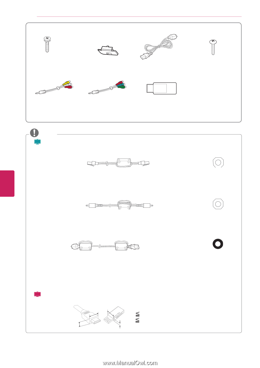
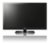
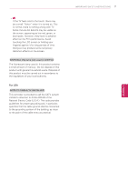
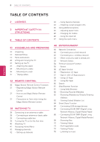
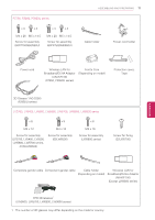
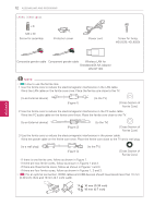
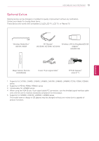
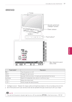
12 ASSEMBLING AND PREPARING LK530, LK550 series x 8 M4 x 20 Screw for assembly Protection cover Power cord Screw for fixing (42LK530, 42LK550) ENEGNLGISH Composite gender cable Component gender cable Wireless LAN for Broadband/DLNA Adaptor (AN-WF100) NOTE yy( Plasma ) How to use the ferrite core 1 Use the ferrite core to reduce the electromagnetic interference in the LAN cable. Wind the LAN cable on the ferrite core once. Place the ferrite core close to the TV. [to an External device] [Figure 1] [to the TV] [Cross Section of Ferrite Core] 2 Use the ferrite core to reduce the electromagnetic interference in the PC audio cable. Wind the PC audio cable on the ferrite core thrice. Place the ferrite core close to the TV. [to an External device] 10 mm (+/-5 mm) [Figure 2] [to the TV] [Cross Section of Ferrite Core] 3 Use the ferrite core to reduce the electromagnetic interference in the power cable. Wind the power cable on the ferrite core once. Place the ferrite core close to the TV and a wall plug. [to a wall plug] [Figure 3] [to the TV] [Cross Section of Ferrite Core] - If there is one ferrite core, follow as shown in Figure 1. - If there are two ferrite cores, follow as shown in Figures 1 and 2. - If there are three ferrite cores, follow as shown in Figures 1 and 3. - If there are four ferrite cores, follow as shown in Figures 1, 2 and 3. yy( LCD ) For an optimal connection, HDMI cables and USB devices should have bezels less than 10 mm (0.39 inch) thick and 18 mm (0.7 inch) width. B A B *A 10 mm (0.39 inch) *B 18 mm (0.7 inch) A
-
 1
1 -
2
-
3
-
4
-
5
-
6
-
 7
7 -
 8
8 -
 9
9 -
 10
10 -
 11
11 -
 12
12 -
 13
13 -
 14
14 -
 15
15 -
 16
16 -
 17
17 -
18
-
19
-
20
-
21
-
22
-
23
-
24
-
25
-
26
-
27
-
28
-
29
-
30
-
31
-
32
-
33
-
34
-
35
-
36
-
37
-
38
-
39
-
40
-
41
-
42
-
43
-
44
-
45
-
46
-
47
-
48
-
49
-
50
-
51
-
52
-
53
-
54
-
55
-
56
-
57
-
58
-
59
-
60
-
61
-
62
-
63
-
64
-
65
-
66
-
67
-
68
-
69
-
70
-
71
-
72
-
73
-
74
-
75
-
76
-
77
-
78
-
79
-
80
-
81
-
82
-
83
-
84
-
85
-
86
-
87
-
88
-
89
-
90
-
91
-
92
-
93
-
94
-
95
-
96
-
97
-
98
-
99
-
100
-
101
-
102
-
103
-
104
-
105
-
106
-
107
-
108
-
109
-
110
-
111
-
112
-
113
-
114
-
115
-
116
-
117
-
118
-
119
-
120
-
121
-
122
-
123
-
124
-
125
-
126
-
127
-
128
-
129
-
130
-
131
-
132
-
133
-
134
-
135
-
136
-
137
-
138
-
139
-
140
-
141
-
142
-
143
-
144
-
145
-
146
-
147
-
148
-
149
-
150
-
151
-
152
-
153
-
154
-
155
-
156
-
157
-
158
-
159
-
160
-
161
-
162
-
163
-
164
-
165
-
166
-
167
-
168
-
169
-
170
-
171
-
172
 |
 |