Lenovo ThinkCentre A58e User Guide - Page 18
Locating parts on the system board, Internal drives, When installing or replacing an internal drive
 |
View all Lenovo ThinkCentre A58e manuals
Add to My Manuals
Save this manual to your list of manuals |
Page 18 highlights
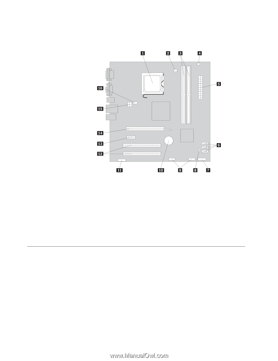
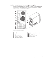
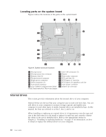
Locating parts on the system board Figure 4 shows the locations of the parts on the system board. Figure 4. System board part locations 1 Microprocessor 2 Microprocessor fan connector 3 Memory slots (2) 4 Thermal sensor connector 5 24-pin power connector 6 SATA connectors (3) 7 Front panel connector 8 Clear CMOS (Complementary Metal Oxide Semiconductor) /Recovery jumper 9 Front USB connectors (2) 10 Battery 11 Front audio connector 12 PCI card slots (2) 13 PCI Express x1 card slot 14 PCI Express x16 graphics card slot 15 4-pin power connector 16 System fan connector Internal drives This section provides information about the internal drives of your computer. Internal drives are devices that your computer uses to read and store data. You can add drives to your computer to increase storage capacity and enable your computer to read other types of media. Internal drives are installed in bays. In this manual, the bays are referred to as bay 1, bay 2, and so on. When installing or replacing an internal drive, it is important to note the type and size of the drive that you can install or replace in each bay and correctly connect the cables to the newly installed drive. Refer to the appropriate section in Chapter 2, "Installing or replacing hardware," on page 13 for instructions on how to install or replace the internal drives for your computer. 10 User Guide
-
 1
1 -
2
-
3
-
4
-
5
-
6
-
7
-
8
-
9
-
10
-
11
-
12
-
 13
13 -
 14
14 -
 15
15 -
 16
16 -
 17
17 -
 18
18 -
 19
19 -
 20
20 -
 21
21 -
 22
22 -
 23
23 -
24
-
25
-
26
-
27
-
28
-
29
-
30
-
31
-
32
-
33
-
34
-
35
-
36
-
37
-
38
-
39
-
40
-
41
-
42
-
43
-
44
-
45
-
46
-
47
-
48
-
49
-
50
-
51
-
52
-
53
-
54
-
55
-
56
-
57
-
58
-
59
-
60
-
61
-
62
-
63
-
64
-
65
-
66
-
67
-
68
-
69
-
70
 |
 |