Lenovo ThinkCentre A58e User Guide - Page 33
Notes, Place the new heat sink and fan assembly on the system board so that the four
 |
View all Lenovo ThinkCentre A58e manuals
Add to My Manuals
Save this manual to your list of manuals |
Page 33 highlights
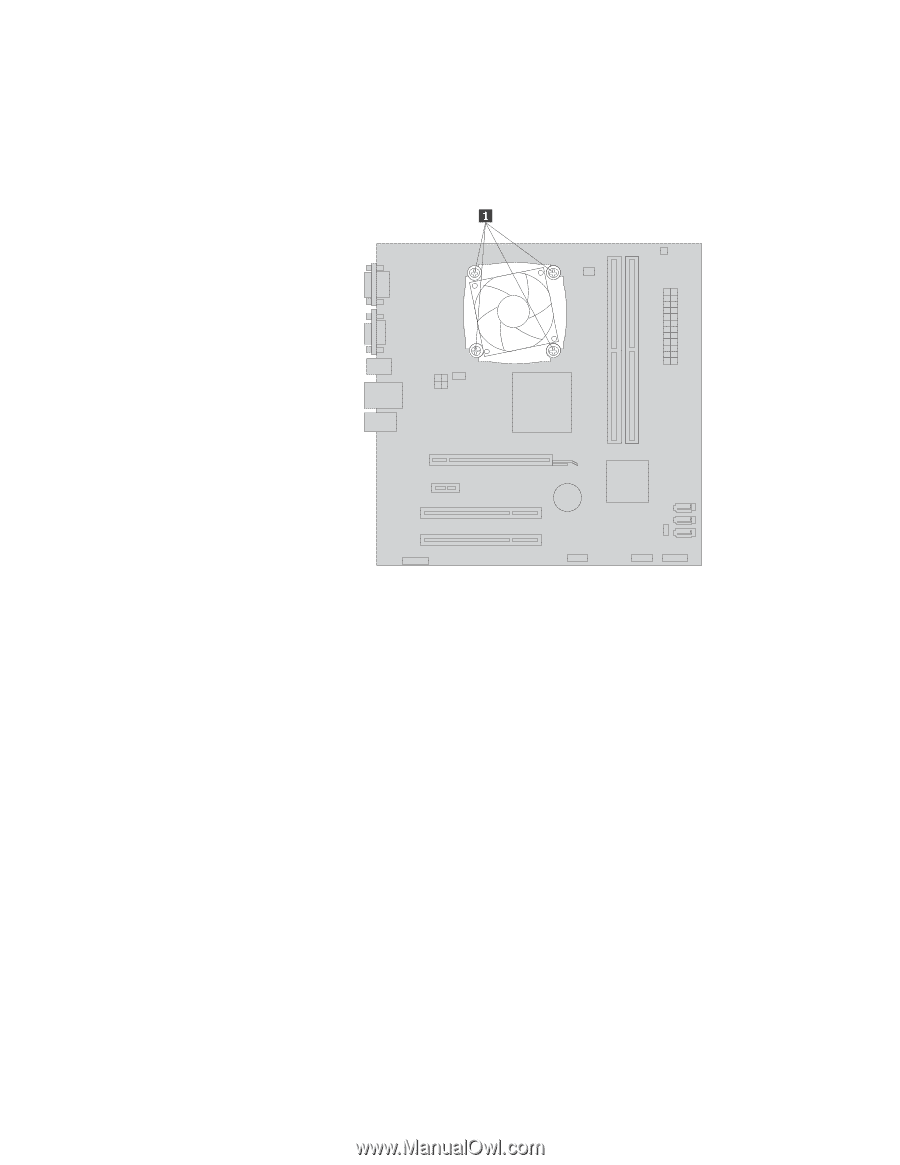
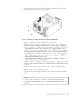
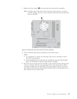
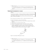
4. Remove the four screws 1 that secure the heat sink and fan assembly. Note: Carefully remove the four screws from the system board to avoid any possible damage. The four screws cannot be removed from the heat sink and fan assembly. Figure 18. Screws that secure the heat sink and fan assembly 5. Lift the old heat sink and fan assembly off the system board. Notes: a. You might have to gently twist the heat sink and fan assembly to free it from the microprocessor. b. When handling the heat sink and fan assembly, do not touch the thermal grease on the bottom of the heat sink and fan assembly. 6. Place the new heat sink and fan assembly on the system board so that the four screws are aligned with the corresponding holes in the system board. Make sure that you place the new heat sink and fan assembly correctly so that you can easily connect the heat sink and fan assembly cable to the microprocessor fan connector on the system board. Chapter 2. Installing or replacing hardware 25
-
 1
1 -
2
-
3
-
4
-
5
-
6
-
7
-
8
-
9
-
10
-
11
-
12
-
13
-
14
-
15
-
16
-
17
-
18
-
19
-
20
-
21
-
22
-
23
-
24
-
25
-
26
-
27
-
 28
28 -
 29
29 -
 30
30 -
 31
31 -
 32
32 -
 33
33 -
 34
34 -
 35
35 -
 36
36 -
 37
37 -
 38
38 -
39
-
40
-
41
-
42
-
43
-
44
-
45
-
46
-
47
-
48
-
49
-
50
-
51
-
52
-
53
-
54
-
55
-
56
-
57
-
58
-
59
-
60
-
61
-
62
-
63
-
64
-
65
-
66
-
67
-
68
-
69
-
70
 |
 |