Lenovo ThinkCentre A58e User Guide - Page 31
What to do next, the chassis.
 |
View all Lenovo ThinkCentre A58e manuals
Add to My Manuals
Save this manual to your list of manuals |
Page 31 highlights
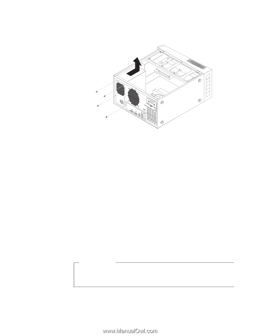
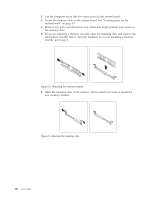
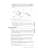
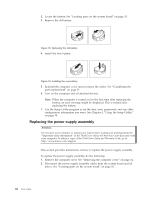
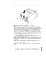
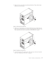
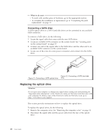
3. Lay the computer on its side and remove the four screws at the rear of the chassis that secure the power supply assembly. Figure 17. Removing the screws that secure the power supply assembly 4. Remove the old power supply assembly out of the chassis. 5. Make sure that the new power supply assembly is the correct replacement. Some power supply assemblies automatically sense the voltage, some power supply assemblies are voltage specific, and some power supply assemblies have a voltage-selection switch. If your computer has a voltage-selection switch, make sure that you set the voltage-selection switch of the new power supply assembly to match the voltage available at your electrical outlet. If necessary, use a ballpoint pen to slide the voltage-selection switch to a different position. v If the voltage supply range in your local country or region is 100-127 V ac, set the voltage-selection switch to 115 V. v If the voltage supply range in your local country or region is 200-240 V ac, set the voltage-selection switch to 230 V. 6. Install the new power supply assembly into the chassis so that the screw holes in the new power supply assembly are aligned with the corresponding holes in the chassis. 7. Install the four screws to secure the new power supply assembly in place. Note: Use only screws provided by Lenovo. 8. Connect the new power supply assembly cables to the system board and all drives. What to do next: v To work with another piece of hardware, go to the appropriate section. v To complete the replacement, go to "Completing the parts replacement" on page 31. Chapter 2. Installing or replacing hardware 23
-
 1
1 -
2
-
3
-
4
-
5
-
6
-
7
-
8
-
9
-
10
-
11
-
12
-
13
-
14
-
15
-
16
-
17
-
18
-
19
-
20
-
21
-
22
-
23
-
24
-
25
-
 26
26 -
 27
27 -
 28
28 -
 29
29 -
 30
30 -
 31
31 -
 32
32 -
 33
33 -
 34
34 -
 35
35 -
 36
36 -
37
-
38
-
39
-
40
-
41
-
42
-
43
-
44
-
45
-
46
-
47
-
48
-
49
-
50
-
51
-
52
-
53
-
54
-
55
-
56
-
57
-
58
-
59
-
60
-
61
-
62
-
63
-
64
-
65
-
66
-
67
-
68
-
69
-
70
 |
 |