MSI K9N2 SLI PLATINUM User Guide - Page 40
Group1, Group2, Group3, Group4 - memory
 |
UPC - 816909045307
View all MSI K9N2 SLI PLATINUM manuals
Add to My Manuals
Save this manual to your list of manuals |
Page 40 highlights
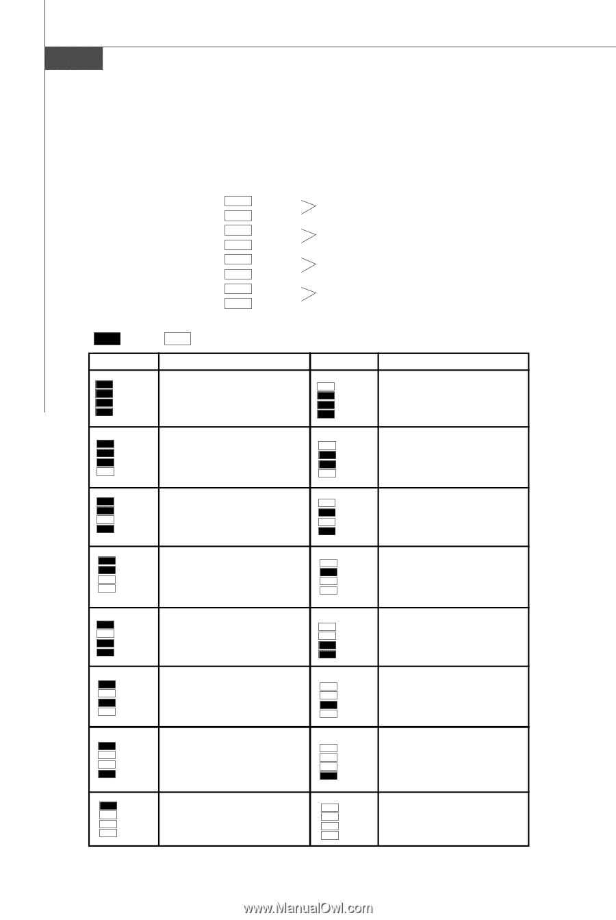
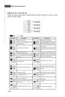
MS-7374 Mainboard LED 4, 5, 6, 7, 8, 9, 10, 11 These four LEDs allow users to identify system problems through 16 various combinations of LED signals. LED4 LED5 LED6 LED7 LED8 LED9 LED10 LED11 Group4 Group3 Group2 Group1 Red LED Signal Group4 Group3 Group2 Group1 Green Description System Power ON The D-LED will hang here if the processor is damaged or not installed properly. LED Signal Description Group4 Group3 Group2 Group1 Initializing Video Interface This will start detecting CPU clock, checking type ofvideo onboard. Then, detect and initializethe video adapter. Group4 Group3 Group2 Group1 Early Chipset Initialization Group4 Group3 Group2 Group1 Memory Detection Test Testing onboard memory size. The D-LED will hang if the memory module is damaged or not installed properly. Group4 Group3 Group2 Group1 Decompressing BIOS image to RAM for fast booting. Group4 Group3 Group2 Group1 BIOS Sign On This will start showing information about logo, processor brand name, etc... Group4 Group3 Group2 Group1 Testing Base and Extended Memory Testing base memory from 240K to 640K and extended memory above 1MB using various patterns. Group4 Group3 Group2 Group1 Assign Resources to all ISA. Group4 Group3 Group2 Group1 Initializing Keyboard Controller. Group4 Group3 Group2 Group1 Testing VGA BIOS This will start writing VGA sign-on message to the screen. Group4 Group3 Group2 Group1 Processor Initialization This will show information regarding the processor (like brand name, system bus, etc...) Group4 Group3 Group2 Group1 Testing RTC (Real Time Clock) 2-26 Group4 Group3 Group2 Group1 Initializing Hard Drive Controller This will initialize IDE drive and controller. Group4 Initializing Floppy Drive Controller Group3 This will initialize Floppy Drive and Group2 Group1 controller. Group4 Group3 Group2 Group1 BootAttempt This will set low stack and boot via INT 19h. Group4 Group3 Group2 Group1 Operating System Booting
-
 1
1 -
2
-
3
-
4
-
5
-
6
-
7
-
8
-
9
-
10
-
11
-
12
-
13
-
14
-
15
-
16
-
17
-
18
-
19
-
20
-
21
-
22
-
23
-
24
-
25
-
26
-
27
-
28
-
29
-
30
-
31
-
32
-
33
-
34
-
 35
35 -
 36
36 -
 37
37 -
 38
38 -
 39
39 -
 40
40 -
 41
41 -
 42
42 -
 43
43 -
 44
44 -
 45
45 -
46
-
47
-
48
-
49
-
50
-
51
-
52
-
53
-
54
-
55
-
56
-
57
-
58
-
59
-
60
-
61
-
62
-
63
-
64
-
65
-
66
-
67
-
68
-
69
-
70
-
71
-
72
-
73
-
74
-
75
-
76
-
77
-
78
-
79
-
80
-
81
-
82
-
83
-
84
-
85
-
86
-
87
-
88
-
89
-
90
-
91
-
92
-
93
-
94
-
95
-
96
-
97
-
98
-
99
-
100
-
101
-
102
-
103
-
104
-
105
-
106
-
107
-
108
-
109
-
110
-
111
-
112
-
113
-
114
-
115
-
116
-
117
-
118
-
119
-
120
-
121
-
122
-
123
-
124
-
125
-
126
-
127
-
128
-
129
-
130
-
131
 |
 |