Magnavox 51MP392H User manual, English (US) - Page 14
Onnecting An, Evice - tube pictures
 |
View all Magnavox 51MP392H manuals
Add to My Manuals
Save this manual to your list of manuals |
Page 14 highlights
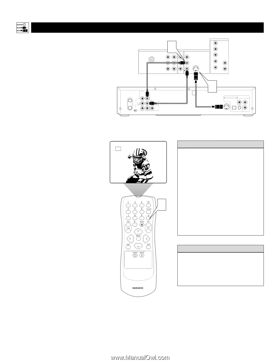
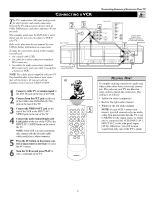
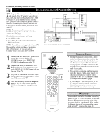
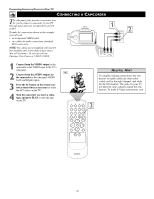
Connecting Accessory Devices to Your TV CONNECTING AN S-VIDEO DEVICE T he S(uper)-Video connection on the rear (and side panel) of the TV can give you better picture detail and clarity for the playback of S-VHS VCR tapes or DVDs than the normal antenna (RF signal) or Video (composite) picture connections. The example given connects a DVD/VCR Combi unit to the INPUT-AV 2 jacks on the rear of the TV. NOTE: The accessory device must have an S-VIDEO output jack to make the connection explained on this page. To make the connections, you will need: • one S-Video cable • two cables for audio connections (standard RCA connectors). NOTE: The cables are not supplied with your TV. You should be able to buy them at most stores that sell electronics. Or you can call our Customer Care Center at 1-800-531-0039. Rear of TV ANTENNA IN 75Ω 2 INPUT-AV 1 OUTPUT Y VIDEO Pb L AUDIO Pr R INPUT-AV 2 VIDEO S-VIDEO L L AUDIO R HD INPUT-AV 4 G/Y R/Pr B/Pb V L SYNC AUDIO H R Rear of Device with S-VIDEO Output* ANT-IN ANT-OUT DVD/VCR OUT IN L AUDIO R DVD/VCR AUDIO OUT L VIDEO R CH3 CH4 *(Example: Philips DVD/VCR Combi model DV910VHS) 1 DIGITAL AUDIO OUT COMPONENT PCM / BITSTREAM VIDEO OUT Y Cr Cb S-VIDEO OPTICAL COAXIAL OUT 1 Connect the S-VIDEO OUT jack on the rear of the accessory device with AV2 S-VIDEO output to the INPUT-AV 2 S-VIDEO jack on the rear of the TV. 2 Connect the DVD/VCR AUDIO OUT jacks on the rear of the accessory device to the INPUT-AV 2 AUDIO input jacks on the rear of the TV. 3 Press the AV button on the remote control as many times as necessary to select the AV2 source on the TV. 4 Turn the accessory device on and press play to view the video source material (DVD or videotape, for example) on the TV. HELPFUL HINTS • To simplify making connections, audio cables are often color coded: red for the right channel, and white for the left channel. The jacks on your TV are likewise color coded to match the connectors. To make S-Video connections, you must use an S-Video cable. • You can also connect a satellite receiver, laser-disc player, video-game player, or other accessory device with S-Video 3 capability to the TV in a manner similar to example shown on this page. • If you connect a satellite receiver to the TV, you will need to use the receiver's channel-memorization system to store channels in the receiver's memory. WARNING Video sources that show a constant nonmoving pattern on the TV screen can cause picture-tube damage. When you are not using your video accessory devices, turn them off. Also, regularly alternate the use of accessory video sources with normal TV viewing. See page 49. 14
-
 1
1 -
2
-
3
-
4
-
5
-
6
-
7
-
8
-
 9
9 -
 10
10 -
 11
11 -
 12
12 -
 13
13 -
 14
14 -
 15
15 -
 16
16 -
 17
17 -
 18
18 -
 19
19 -
20
-
21
-
22
-
23
-
24
-
25
-
26
-
27
-
28
-
29
-
30
-
31
-
32
-
33
-
34
-
35
-
36
-
37
-
38
-
39
-
40
-
41
-
42
-
43
-
44
-
45
-
46
-
47
-
48
-
49
-
50
-
51
-
52
-
53
-
54
-
55
-
56
 |
 |