Magnavox 51MP392H User manual, English (US) - Page 9
Connecting - manual
 |
View all Magnavox 51MP392H manuals
Add to My Manuals
Save this manual to your list of manuals |
Page 9 highlights
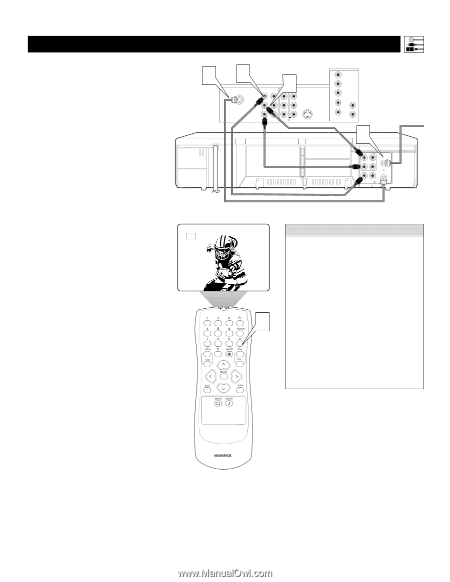
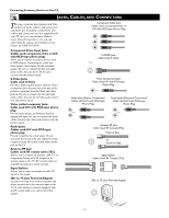
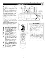
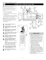
CONNECTING A VCR Connecting Accessory Devices to Your TV T he TV's audio/video (AV) input jacks provide for direct picture and sound connections between the TV and accessory devices such as VCRs, DVD players, and others that have AV output jacks. This example, which uses the INPUT-AV 1 jacks, shows you one way you can connect a VCR to your TV. Refer to the directions-for-use manual for your VCR for further information on connections. To make the connections shown in this example, you will need: • one coaxial cable (75Ω) • one cable for a video connection (standard RCA connector) • two cables for audio connections (standard RCA connectors) (only one cable is needed for a nonstereo VCR). NOTE: The cables are not supplied with your TV. You should be able to buy them at most stores that sell electronics. Or you can call our Customer Care Center at 1-800-531-0039 2 Rear of VCR* * (Example: Philips VCR model VR674CAT) AV1 1 Connect a cable TV or antenna signal to the ANT IN jack on the rear of the VCR. 2 Connect from the OUT jack on the rear of the VCR to the ANTENNA IN 75Ω jack on the rear of the TV. 3 Connect the VIDEO OUT jack on the rear of the VCR to the INPUT AV1 VIDEO jack on the rear of the TV. 4 Connect the audio output R(ight) and L(eft) jacks on the rear of the VCR to the INPUT-AV 1 AUDIO jacks on the rear of the TV. NOTE: If the VCR is a mono (nonstereo) unit, connect only the left audio cable, which usually has a white connector. 5 Press the AV button on the remote control as many times as necessary to select the AV1 source. 6 Turn the VCR on and press PLAY to view a videotape on the TV. 3 ANTENNA IN 75Ω INPUT-AV 1 VIDEO L AUDIO R Rear of TV 4OUTPUT INPUT-AV 2 Y VIDEO S-VIDEO Pb L L Pr AUDIO R HD INPUT-AV 4 G/Y R/Pr B/Pb V L SYNC AUDIO H R Coaxial Cable Lead-in from Cable TV Company or VHF/UHF Antenna 1 AUDIO L OUT IN R VIDEO ANT IN OUT OUT IN CH3 CH4 HELPFUL HINT To simplify making connections, audio and video cables often have color-code connectors. The jacks on your TV are likewise color coded to match the connectors. The coding is as follows: • Yellow for video (composite) • Red for the right audio channel • White for the left audio channel 5 NOTE: If your VCR is mono (nonstereo), you will connect only one audio cable. You must ensure that the TV is set to MONO for the signal source to which you've connected the VCR (INPUT-AV 1, INPUT-AV2, or the side panel inputs [AV3]). Otherwise, you will receive sound from only one of the TV's speak- 9
-
 1
1 -
2
-
3
-
 4
4 -
 5
5 -
 6
6 -
 7
7 -
 8
8 -
 9
9 -
 10
10 -
 11
11 -
 12
12 -
 13
13 -
 14
14 -
15
-
16
-
17
-
18
-
19
-
20
-
21
-
22
-
23
-
24
-
25
-
26
-
27
-
28
-
29
-
30
-
31
-
32
-
33
-
34
-
35
-
36
-
37
-
38
-
39
-
40
-
41
-
42
-
43
-
44
-
45
-
46
-
47
-
48
-
49
-
50
-
51
-
52
-
53
-
54
-
55
-
56
 |
 |