Motorola SB5100 Installation Manual - Page 14
Rear Panel, SURFboard Cable Modem Installation Manual, Rear-panel connections and LEDs - cable modem manual
 |
UPC - 612572073193
View all Motorola SB5100 manuals
Add to My Manuals
Save this manual to your list of manuals |
Page 14 highlights
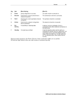
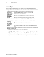
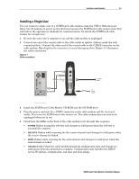
2-4 Overview Rear Panel The SURFboard cable modem rear panel provides the cabling connectors, status LEDs, and power plug as illustrated in Figure 2-3: Figure 2-3 Rear-panel connections and LEDs ETHERNET USB 1 2 3 CABLE CUSTOMER S/N:BCDFGHJKLMNP S/N: PPPPMMYJJJSSSSSCAABBCCCC HFC MAC ID: ABCDEF012345 USB CPE MAC ID:ABDCEF012345 4 +12VDC Table 2-2 describes the SURFboard cable modem rear-panel connections and LEDs: Table 2-2 Rear-panel connections and LEDs Key Item 1 ETHERNET 2 USB 3 CABLE 4 +12VDC Description The Ethernet port provides a connection to Ethernet equipped computers using a cable terminated with an RJ-45 connector. This port provides a direct connection to USB equipped computers. This port provides a connection to the coaxial cable outlet. This connector provides power to the cable modem. SURFboard Cable Modem Installation Manual
-
 1
1 -
2
-
3
-
4
-
5
-
6
-
7
-
8
-
 9
9 -
 10
10 -
 11
11 -
 12
12 -
 13
13 -
 14
14 -
 15
15 -
 16
16 -
 17
17 -
 18
18 -
 19
19 -
20
-
21
-
22
-
23
-
24
-
25
-
26
-
27
-
28
-
29
-
30
-
31
-
32
-
33
-
34
-
35
-
36
-
37
-
38
-
39
-
40
-
41
-
42
-
43
-
44
-
45
-
46
-
47
-
48
-
49
-
50
-
51
-
52
-
53
-
54
-
55
-
56
-
57
-
58
-
59
-
60
-
61
-
62
-
63
-
64
-
65
-
66
-
67
-
68
-
69
-
70
-
71
-
72
-
73
-
74
-
75
-
76
-
77
-
78
-
79
-
80
-
81
-
82
-
83
-
84
-
85
-
86
-
87
-
88
-
89
-
90
-
91
-
92
-
93
-
94
-
95
-
96
-
97
-
98
-
99
-
100
 |
 |