Panasonic WJRT416V WJRT416V User Guide - Page 49
RS485 (CAMERA) port, AUDIO IN/ALARM OUT terminal, RS485CAMERA
 |
View all Panasonic WJRT416V manuals
Add to My Manuals
Save this manual to your list of manuals |
Page 49 highlights
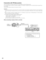
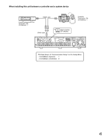
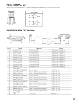
RS485 (CAMERA) port When connecting an RS485 camera, connect it to the RS485 (CAMERA) port on the rear of the recorder. RS485(CAMERA) Block diagram RA RB TA Signal TA TB RA RB Signal GND GND OUT IN TB AUDIO IN/ALARM OUT terminal !3 q Control circuit AUDIO IN/ALARM OUT @5 !4 Normally close output Common output Normally open output Internal block diagram In normal state At an alarm occurrence Pin No. q w e r t y u i o !0 !1 !2 !3 !4 !5 !6 !7 !8 !9 @0 @1 @2 @3 @4 @5 Signal Audio input CH7 Audio input CH8 Audio input CH9 Audio input CH10 Audio input CH11 Audio input CH12 Audio input CH13 Audio input CH14 Audio input CH15 Audio input CH16 (Signal GND) Alarm 1 Output (COMMON) Alarm 1 Output (NO) Alarm 1 Output (NC) Alarm 2 Output (COMMON) Alarm 2 Output (NO) Alarm 2 Output (NC) Alarm 3 Output (COMMON) Alarm 3 Output (NO) Alarm 3 Output (NC) Alarm 4 Output (COMMON) Alarm 4 Output (NO) Alarm 4 Output (NC) (Signal GND) +12 V Operation Audio input (CH7) Audio input (CH8) Audio input (CH9) Audio input (CH10) Audio input (CH11) Audio input (CH12) Audio input (CH13) Audio input (CH14) Audio input (CH15) Audio input (CH16) Common output 1 Output 1, Normally open-collector Output 1, Normally closed-collector Common output 2 Output 2, Normally open-collector Output 2, Normally closed-collector Common output 3 Output 3, Normally open-collector Output 3, Normally closed-collector Common output 4 Output 4, Normally open-collector Output 4, Normally closed-collector +12 V output Remark -10 dBv 51 kΩ, unbalanced -10 dBv 51 kΩ, unbalanced -10 dBv 51 kΩ, unbalanced -10 dBv 51 kΩ, unbalanced -10 dBv 51 kΩ, unbalanced -10 dBv 51 kΩ, unbalanced -10 dBv 51 kΩ, unbalanced -10 dBv 51 kΩ, unbalanced -10 dBv 51 kΩ, unbalanced -10 dBv 51 kΩ, unbalanced 1 A, 30 V DC max. 1 A, 30 V DC max. 1 A, 30 V DC max. 1 A, 30 V DC max. 1 A, 30 V DC max. 1 A, 30 V DC max. 1 A, 30 V DC max. 1 A, 30 V DC max. 1 A, 30 V DC max. 1 A, 30 V DC max. 1 A, 30 V DC max. 1 A, 30 V DC max. 800 mA max. 49
-
 1
1 -
2
-
3
-
4
-
5
-
6
-
7
-
8
-
9
-
10
-
11
-
12
-
13
-
14
-
15
-
16
-
17
-
18
-
19
-
20
-
21
-
22
-
23
-
24
-
25
-
26
-
27
-
28
-
29
-
30
-
31
-
32
-
33
-
34
-
35
-
36
-
37
-
38
-
39
-
40
-
41
-
42
-
43
-
 44
44 -
 45
45 -
 46
46 -
 47
47 -
 48
48 -
 49
49 -
 50
50 -
 51
51 -
 52
52 -
 53
53 -
 54
54 -
55
-
56
-
57
-
58
-
59
-
60
-
61
-
62
-
63
-
64
-
65
-
66
-
67
-
68
-
69
-
70
-
71
-
72
-
73
-
74
-
75
-
76
-
77
-
78
-
79
-
80
 |
 |
