Panasonic WJRT416V WJRT416V User Guide - Page 50
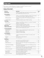
ALARM IN/CONTROL terminal, Pin No., Signal, Operation, Remark
 |
View all Panasonic WJRT416V manuals
Add to My Manuals
Save this manual to your list of manuals |
Page 50 highlights
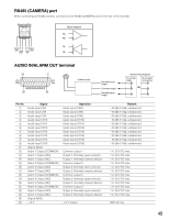
ALARM IN/CONTROL terminal !3 q Pin No. Signal q Alarm input CH1 w Alarm input CH2 e Alarm input CH3 r Alarm input CH4 t Alarm input CH5 y Alarm input CH6 u Alarm input CH7 i Alarm input CH8 o Alarm input CH9 !0 Alarm input CH10 !1 Alarm input CH11 !2 Alarm input CH12 !3 Alarm input CH13 !4 Alarm input CH14 !5 Alarm input CH15 !6 Alarm input CH16 !7 Time adjust input !8 Error output !9 @0 - @4 @5 HDD error output (Signal GND) (N.C.) ALARM IN/CONTOROL @5 !4 Operation An event action will be taken according to the setting. An event action will be taken according to the setting. An event action will be taken according to the setting. An event action will be taken according to the setting. An event action will be taken according to the setting. An event action will be taken according to the setting. An event action will be taken according to the setting. An event action will be taken according to the setting. An event action will be taken according to the setting. An event action will be taken according to the setting. An event action will be taken according to the setting. An event action will be taken according to the setting. An event action will be taken according to the setting. An event action will be taken according to the setting. An event action will be taken according to the setting. An event action will be taken according to the setting. The clock of the recorder will be set to 00 (min) by signal input. (Time correction range: ±15 minutes) Signal output upon an error detection (Thermal error (47 °C {117 °F} or higher), fan error, video loss, password entry failure (3 times straight incorrect password entry), no HDD detection) Signal output upon a HDD error detection Remark Non-voltage make contact input, pulse width: 100 ms or more Non-voltage make contact input, pulse width: 100 ms or more Non-voltage make contact input, pulse width: 100 ms or more Non-voltage make contact input, pulse width: 100 ms or more Non-voltage make contact input, pulse width: 100 ms or more Non-voltage make contact input, pulse width: 100 ms or more Non-voltage make contact input, pulse width: 100 ms or more Non-voltage make contact input, pulse width: 100 ms or more Non-voltage make contact input, pulse width: 100 ms or more Non-voltage make contact input, pulse width: 100 ms or more Non-voltage make contact input, pulse width: 100 ms or more Non-voltage make contact input, pulse width: 100 ms or more Non-voltage make contact input, pulse width: 100 ms or more Non-voltage make contact input, pulse width: 100 ms or more Non-voltage make contact input, pulse width: 100 ms or more Non-voltage make contact input, pulse width: 100 ms or more Non-voltage make contact input, pulse width: 100 ms or more Open collector output, 100 mA or less, 24 V DC max. Open collector output, 100 mA or less, 24 V DC max. Not available 50
-
 1
1 -
2
-
3
-
4
-
5
-
6
-
7
-
8
-
9
-
10
-
11
-
12
-
13
-
14
-
15
-
16
-
17
-
18
-
19
-
20
-
21
-
22
-
23
-
24
-
25
-
26
-
27
-
28
-
29
-
30
-
31
-
32
-
33
-
34
-
35
-
36
-
37
-
38
-
39
-
40
-
41
-
42
-
43
-
44
-
 45
45 -
 46
46 -
 47
47 -
 48
48 -
 49
49 -
 50
50 -
 51
51 -
 52
52 -
 53
53 -
 54
54 -
 55
55 -
56
-
57
-
58
-
59
-
60
-
61
-
62
-
63
-
64
-
65
-
66
-
67
-
68
-
69
-
70
-
71
-
72
-
73
-
74
-
75
-
76
-
77
-
78
-
79
-
80
 |
 |
